Monkey Ball
Amusement Vision (2001)
🔗Known Hardware
Naomi
- Monkey Ball
🔗Known Parts
No known parts for this game.
🔗Images and Diagrams
No images currently added.
🔗Repair Manuals
No manuals currently added.
🔗Repair Tips
🔗 Analog Stick Wiring for New Net City
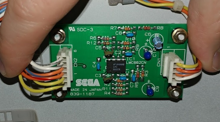
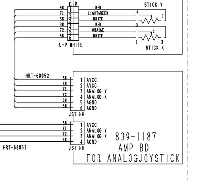
The analog stick panel connects to a NNC over the 1P auxiliary analog interface as well as the 1P digital controls interface. The joystick is fed through an interface board (839-1187) which is effectively a dual op-amp circuit. It takes divided input from a pair of potentiometers and translates to an analog XY signal. The correct JST NH connectors for the board are H4P-SHF-AA and H6P-SHF-AA and the correct pins are SHF-001T-0.8BS. They are crimped, so be sure to get a pair of crimpers. The correct wiring colors for the connectors can be seen here: On the 6 pin side, the outer two wires on each side are the VREF (1 and 2 pins) and GND (5 and 6 pins) wires to the horizontal and vertical potentiometer. Pin 3 (the orange and red wire) goes to the vertical potentiometer center tap. Pin 4 (the orange and blue wire) goes to the horizontal potentiometer center tap. On the 4 pin side, pin 1 (the yellow wire) is VREF, pin 2 (the orange and red wire) is joystick Y position, pin 3 (the orange and gray wire) is joystick X position and pin 4 (the white wire) is GND.See the following diagram for more information:
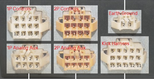
 Connections on the NNC side are as follows:
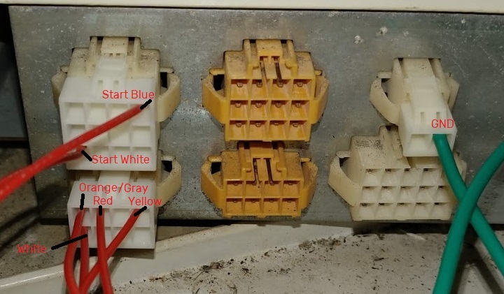
 The start button wires go to the 1P controls connection. Pin 1 maps to start button blue and pin 12 maps to start button white. According to arcade otaku wiki, these correspond to 1P start and GND, respectively. The analog controls map to the 1P analog aux connection and come from the 4-pin connector on the analog interface board. Pin 1 maps to the yellow wire, pin 3 maps to the orange and red wire, pin 4 maps to the orange and gray wire, and pin 8 maps to the white wire. Finally, if you are going to do things correctly, the earth ground connected to the panel itself should go to either pin 1 or 2 of the earth ground connector (either will do).The correct TE AMP part numbers for the connectors are 176271-1 for the earth ground, 176275-1 for the analog aux, 176278-1 for the controls, 175151-1 for the controls/analog pins and 175152-1 for the ground pin (thicker since the ground connection is a thicker gauge wire). Again, you'll need a set of crimpers for these.An example crimped set of connectors looks like the following:
 On the 6 pin side, the outer two wires on each side are the VREF (1 and 2 pins) and GND (5 and 6 pins) wires to the horizontal and vertical potentiometer. Pin 3 (the orange and red wire) goes to the vertical potentiometer center tap. Pin 4 (the orange and blue wire) goes to the horizontal potentiometer center tap. On the 4 pin side, pin 1 (the yellow wire) is VREF, pin 2 (the orange and red wire) is joystick Y position, pin 3 (the orange and gray wire) is joystick X position and pin 4 (the white wire) is GND.See the following diagram for more information:
 Connections on the NNC side are as follows:
 The start button wires go to the 1P controls connection. Pin 1 maps to start button blue and pin 12 maps to start button white. According to arcade otaku wiki, these correspond to 1P start and GND, respectively. The analog controls map to the 1P analog aux connection and come from the 4-pin connector on the analog interface board. Pin 1 maps to the yellow wire, pin 3 maps to the orange and red wire, pin 4 maps to the orange and gray wire, and pin 8 maps to the white wire. Finally, if you are going to do things correctly, the earth ground connected to the panel itself should go to either pin 1 or 2 of the earth ground connector (either will do).The correct TE AMP part numbers for the connectors are 176271-1 for the earth ground, 176275-1 for the analog aux, 176278-1 for the controls, 175151-1 for the controls/analog pins and 175152-1 for the ground pin (thicker since the ground connection is a thicker gauge wire). Again, you'll need a set of crimpers for these.An example crimped set of connectors looks like the following: