Twinkle
Konami (2000)
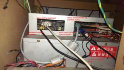
The hardware stack used to run the original IIDX games. It has an IDE hard drive for key sounds, a SCSI CD-ROM for the boot media, a security chip for anti-piracy and a serial connection to an external DVD player for video playback. It handles the video mixing from the DVD player and all of the IO so no additional boards such as a USBIO are required.
🔗Known Games
beatmania IIDX
- Beatmania IIDX (GQ863)
- Beatmania IIDX 2nd Style (GC985)
- Beatmania IIDX 3rd Style (GC992)
- Beatmania IIDX 4th Style (__A03)
- Beatmania IIDX 5th Style (GCA17)
- Beatmania IIDX 6th Style (GCB4U)
- Beatmania IIDX 7th Style (__B44)
- Beatmania IIDX 8th Style (GCC44)
- Beatmania IIDX Club Version (__896)
- Beatmania IIDX Club Version 2 (GE984)
- Beatmania IIDX Substream (GC983/GE983)
🔗Known Parts
No known parts for this hardware.
🔗Images and Diagrams

🔗Repair Manuals
No manuals currently added.
🔗Repair Tips
🔗 Replacing the SCSI CD-ROM
As is the case with most older Konami hardware, the Twinkle is finicky with replacement CD-ROM devices. If you purchase the wrong one, it may boot but take longer to load and occasionally error out with a SCSI timeout message. This is harmless but annoying.A TEAC CD-516S 16X SCSI CD-ROM drive has been tested working for several days in Twinkle hardware. A TEAC CD-532S has also been verified to work. When swapping the drives, you will have to disassemble pretty much the entire stack since they placed the nuts holding the drive bay in an awkward position. Make sure the new drive is set to SCSI ID 4 and has TERM and PARITY jumped.
🔗 IIDX 1st Style DVD Connection
Substream through 8th style connect to the external DVD player through standard serial (DB9). 1st style, for some reason, uses the MINIDIN-8 port. It is a proprietary pinout that requires RTS/CTS connected in order to pass checks. This is a tested working diagram for the pinout to connect a DVD player to a Twinkle to play background movies on 1st Style. Colors are arbitrary to highlight the correct pins:
- Pin 1 (red) - RX
- Pin 2 (green) - RTS
- Pin 3 (blue) - TX
- Pin 4 (yellow) - CTS
- Pin 5 - NC
- Pin 6 - NC
- Pin 7 - (brown) Ground
- Pin 8 - (brown) Ground