Konami IO-2 USBIO
unknown, original
Pop'n HD cabinets use a variant called "IO-2-R", which presumably has modifications to eliminate the warm up voltage for the lamps.Pop'n SD cabinet variants of the IO-2 have 4 dipswitches, among which only the 4th one has a known use. When windows starts it runs a program called "boot.exe" which reads the DIP4 value. If it is in the up position, resolution is changed to a 480i 60Hz 15 kHz signal. If it is in the down position or if no IO-Board was found, it switches to a 480p 60Hz signal (this mode is mislabeled as 75Hz in the graphics device driver, but signal has been confirmed to be indeed 60Hz. This was probably done as a hack so they could switch between 15kHz or 31kHz signals by using values "60" or "75" in the ChangeDisplaySettingsEx() windows API call).Note: older Pop'n Music cabinets (type A, B and C) have a video amp on the power distribution board (aka "relay circuit box"), which led to a common misconception that the IO-2 was processing video signals. In reality, for these cabinets the video signal was fed directly from the PC motherboard to the power distribution board. The IO-2 itself has no means to process video signals.
🔗Known Vendors
No known vendors for this part.
🔗Games Using This Part
🔗Hardware Using This Part
🔗Images and Diagrams
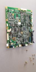
Full view of the Konami IO-2 USBIO
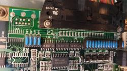
Fuses and transistors near the main connector
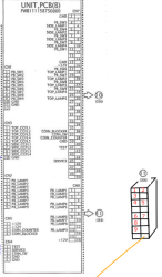
power distribution board bypass diagram
🔗Repair Manuals
No manuals currently added.
🔗Repair Tips
🔗 Measurements and Diagnostic
Rather than measuring voltage on the leds directly, it is better to take measurments from the IOBoard2 connector as it will help diagnose the most common errors.Run dupont connectors straight into the "CN2" connector and go into the game test menu. You should measure 0V when the light is off and 12V when it's on.- If it's always 0V it's either a fuse or transistor issue- If it's always 12V or you have funky values like 0.15V(off) 0.56V(on), or 0.3V(off) 3.3V(on), it's a transistor issue- If you have 0V/12V but the button lamp is not working ingame, then the issue is on the power distribution board (I suggest doing the LED mod in this case as it will solve the issue as well)
🔗 LED mod (replacing lightbulbs with LEDs)
While the IOBoard signal is 0V/12V, incandescent lightbulbs would die quickly if they were to be turned on and off this much. For that reason the power distribution board inserts a series resistance of approximately 850 ohms when the lights are commanded off. This generates a keepwarm voltage providing ~14 mA of short circuit current and the signal becomes 0.13V/12V when loaded with an incandescent lightbulb.For that reason, replacing the lightbulbs with 12V LEDs make the buttons always lit because the additional series resistance provided while the lights are commanded off is not enough to sufficiently reduce current flow to the LEDs and completely turn them off.The keepwarm voltage is generated by 9 resistors on the power distribution board labeled R1 to R9, one for each button. The 12V goes through the resistor before being sent to the lamp so there's a constant ~14 mA from lamp to ground. When the IOboard commands the light on (i.e. bypassing the series resistance), the lamp gets directly connected to 12V.You can either desolder these resistances from the power distribution board, or bypass by wiring CN2 connector from BemaniPC side directly to the plugs which goes into the CN8 connector on the power distribution board (see above picture, unplug the circled 11 connector from the power distribution board, then plug dupont cables directly inside that connector which runs straight to the control panel lamps).
🔗 Replacing Transistors
A little bit above the fuses are four 2-transistor chips labeled U51 U52 U57 U58. You can test these with a multimeter.You can replace them with AO4800B. (AO4800B is now obsolete, but the manufacturer recommends AOSD32334C as a replacement, although this has not been verified.)
🔗 Replacing Fuses
There are 16 fuses near the connector, labeled F1-16. The first 8 fuses are for the buttons (except red button).You can replace them with SMD 0805 2012 12V 1.1A fuses.