jubeat
Konami (2008-2025)
There appear to be two main variants of the jubeat casing: a pre-L44 build (I44, J44, etc...) and an L44-build cabinet. jubeat before L44 used a P3IO for its input, but switched to a P4IO with L44. Cabinets that were built before L44 had their P3IO with a JAMMA edge connector, which allowed for an easy upgrade to the P4IO with L44 upgrade kit.Cabinets that were built for L44 don't have an edge connector, and have the P4IO built into the casing.
🔗Known Hardware
Bemani PC (ADE-6291)
- Latest revision cabinets using Windows 7 Embedded run this board.
Bemani PC (ADE-704A)
- jubeat Qubell (L44)
- jubeat clan (L44)
- jubeat festo (L44).
- jubeat prop (L44)
- jubeat saucer (fulfill) (L44)
Bemani PC Type 3 (Variant C)
- jubeat copious (APPEND)
- jubeat knit (APPEND)
- jubeat ripples (APPEND)
🔗Known Parts
- Jubeat (ZhouSensor) Rubber Button
- Jubeat Blower Fan (replacement)
- Konami P3IO
- Konami P4IO
- LG D26L155
- SHARP LFM255KP-264
- SHARP LFM255XL-251
🔗Images and Diagrams
No images currently added.
🔗Repair Manuals
🔗Repair Tips
🔗 Disassembling the Front Panel
In order to clean dirt and spills, as well as to repair misfiring panels and replace broken sensors, you will need to disassemble the front panel. This is probably one of the worst games to disassemble in terms of how complicated it is to get to the serviceable parts.First, you will want to unscrew and remove the decorative side panels. There should be two screws on the front of the cab on each side, two on back on each side, and two near the control panel on each side. This shows the screw location for the right side panel control panel screws: Once you have both of these panels off, you will want to remove the front decorative panel and the decorative panel in the center of the screen. Both should have two screws:
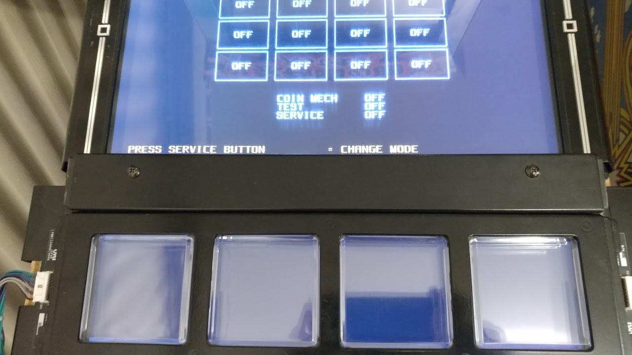 Now that the decorative panels are off, you should have access to the wiring underneath. You can unplug the wires from the four connectors now. Note that you can do this with the cabinet running. I do so with the test screen up so I can reattach and test repairs before fully reassembling. Once the connectors have been unplugged (four on each side), three screws on the top and three screws on the bottom of the assembly hold it in. Unscrew them:
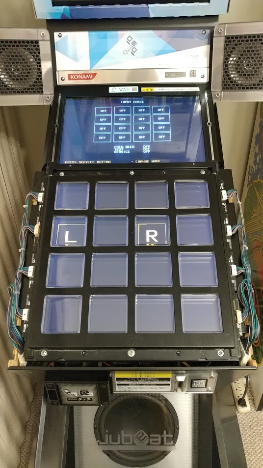 You should be able to remove the whole assembly at this point. Flip it over. If there is a protective rubber cover, remove it at this point. You should have a panel that looks similar to the following:
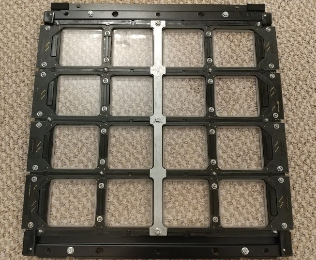 Now that you have access to this, the first thing you need to remove is the center brace. This secures the center part of each of the 8 sensor boards. Remove the three nuts that hold it down. Now is a good time to remove the other nuts holding down various parts of the circuit board. Do not remove the two nuts on the very top and two nuts on the very bottom of the assembly. These hold the front decorative plate to the back, and if you remove them all of the panels and rubbers will fall out everywhere and you will be so sad. Your panel should look like this now:
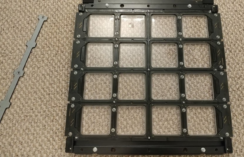 Removing each sensor board is as simple as removing the four screws that hold it. A detail of one sensor board with the four screws that hold it is shown below. Note that if you are trying to repair a single panel, you only need to remove the circuit that covers it and its neighbor.
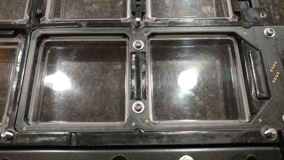 Once you remove the circuit board, the rubbers that make contact with the PCB will be exposed. Make sure that none of them are broken or dirty. Sometimes the actual plunger piece can get torn off and fall into the cabinet or get bent. Replace these rubbers with new ones if this happens. Failing to do so can cause a misfiring or sticking panel.
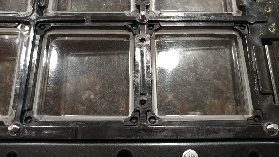 At this point, you can clean the PCBs and rubbers in order to prolong their life and replace any that have broken. Note that if you are cleaning the rubbers themselves, do not use alcohol. This dries out the carbon contact and causes brittleness. Simply use warm water on a q-tip to swab them clean. On the PCB, you can clean with a q-tip and alcohol. If you have a particularly nasty stain or lots of dirt build-up, you can use a pink erasor as an abrasive with rubbing alcohol as the solvent to shine up the contacts before making one last past with a q-tip and alcohol.When you re-assemble, pay no attention to the order in which you put on the PCBs. They are interchangeable, and the wires can only reach to the correct location for the panel. If you put the sides back on backwards the screws that normally go to the control panel will be at the bottom. Just reverse the panels and you are good to go. You can test on the go by partially re-assembling and plugging in the wires to check your work.
Once you have both of these panels off, you will want to remove the front decorative panel and the decorative panel in the center of the screen. Both should have two screws:Now that the decorative panels are off, you should have access to the wiring underneath. You can unplug the wires from the four connectors now. Note that you can do this with the cabinet running. I do so with the test screen up so I can reattach and test repairs before fully reassembling. Once the connectors have been unplugged (four on each side), three screws on the top and three screws on the bottom of the assembly hold it in. Unscrew them:You should be able to remove the whole assembly at this point. Flip it over. If there is a protective rubber cover, remove it at this point. You should have a panel that looks similar to the following:Now that you have access to this, the first thing you need to remove is the center brace. This secures the center part of each of the 8 sensor boards. Remove the three nuts that hold it down. Now is a good time to remove the other nuts holding down various parts of the circuit board. Do not remove the two nuts on the very top and two nuts on the very bottom of the assembly. These hold the front decorative plate to the back, and if you remove them all of the panels and rubbers will fall out everywhere and you will be so sad. Your panel should look like this now:Removing each sensor board is as simple as removing the four screws that hold it. A detail of one sensor board with the four screws that hold it is shown below. Note that if you are trying to repair a single panel, you only need to remove the circuit that covers it and its neighbor.Once you remove the circuit board, the rubbers that make contact with the PCB will be exposed. Make sure that none of them are broken or dirty. Sometimes the actual plunger piece can get torn off and fall into the cabinet or get bent. Replace these rubbers with new ones if this happens. Failing to do so can cause a misfiring or sticking panel.At this point, you can clean the PCBs and rubbers in order to prolong their life and replace any that have broken. Note that if you are cleaning the rubbers themselves, do not use alcohol. This dries out the carbon contact and causes brittleness. Simply use warm water on a q-tip to swab them clean. On the PCB, you can clean with a q-tip and alcohol. If you have a particularly nasty stain or lots of dirt build-up, you can use a pink erasor as an abrasive with rubbing alcohol as the solvent to shine up the contacts before making one last past with a q-tip and alcohol.When you re-assemble, pay no attention to the order in which you put on the PCBs. They are interchangeable, and the wires can only reach to the correct location for the panel. If you put the sides back on backwards the screws that normally go to the control panel will be at the bottom. Just reverse the panels and you are good to go. You can test on the go by partially re-assembling and plugging in the wires to check your work.🔗 Cleaning The Screen
Assuming you've followed the instructions on how to disassemble the front panel, you should have a Jubeat that has a protective plastic cover over the screen and nothing else, like so: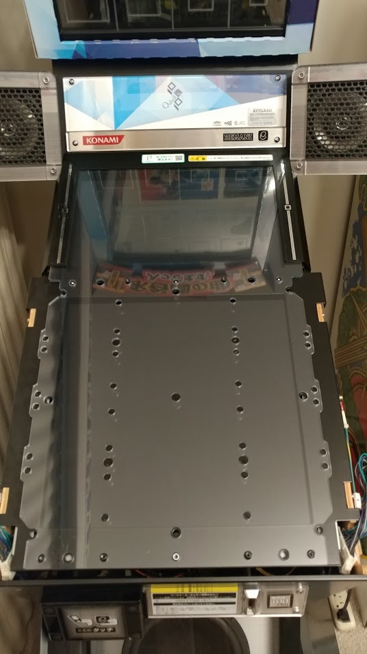 There is usually a lot of dirt and dust underneath it so you might want to clean it. To get access to the plexi itself, you need to remove the top decorative panel. There are two screws on the left and two on the right, as pictured:
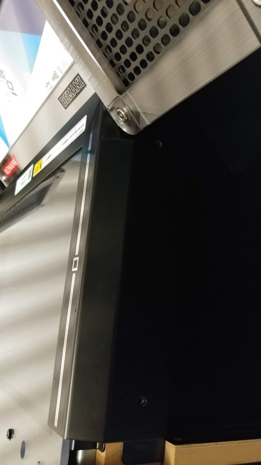 Once you remove them, the plexi can be simply lifted off to reveal the screen below. Hit it with some Windex and then put the plexi back on. The screen will look something like the following with all panels off. There's still some metal over it, but its accessible enough to clean:
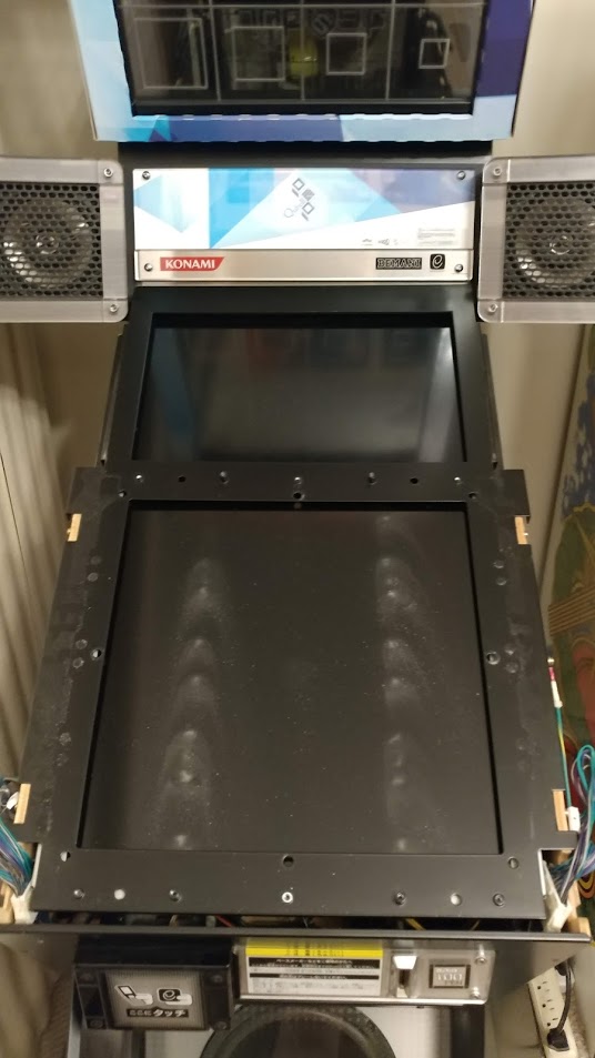
There is usually a lot of dirt and dust underneath it so you might want to clean it. To get access to the plexi itself, you need to remove the top decorative panel. There are two screws on the left and two on the right, as pictured:Once you remove them, the plexi can be simply lifted off to reveal the screen below. Hit it with some Windex and then put the plexi back on. The screen will look something like the following with all panels off. There's still some metal over it, but its accessible enough to clean:🔗 Cleaning/Replacing the Blower Fans
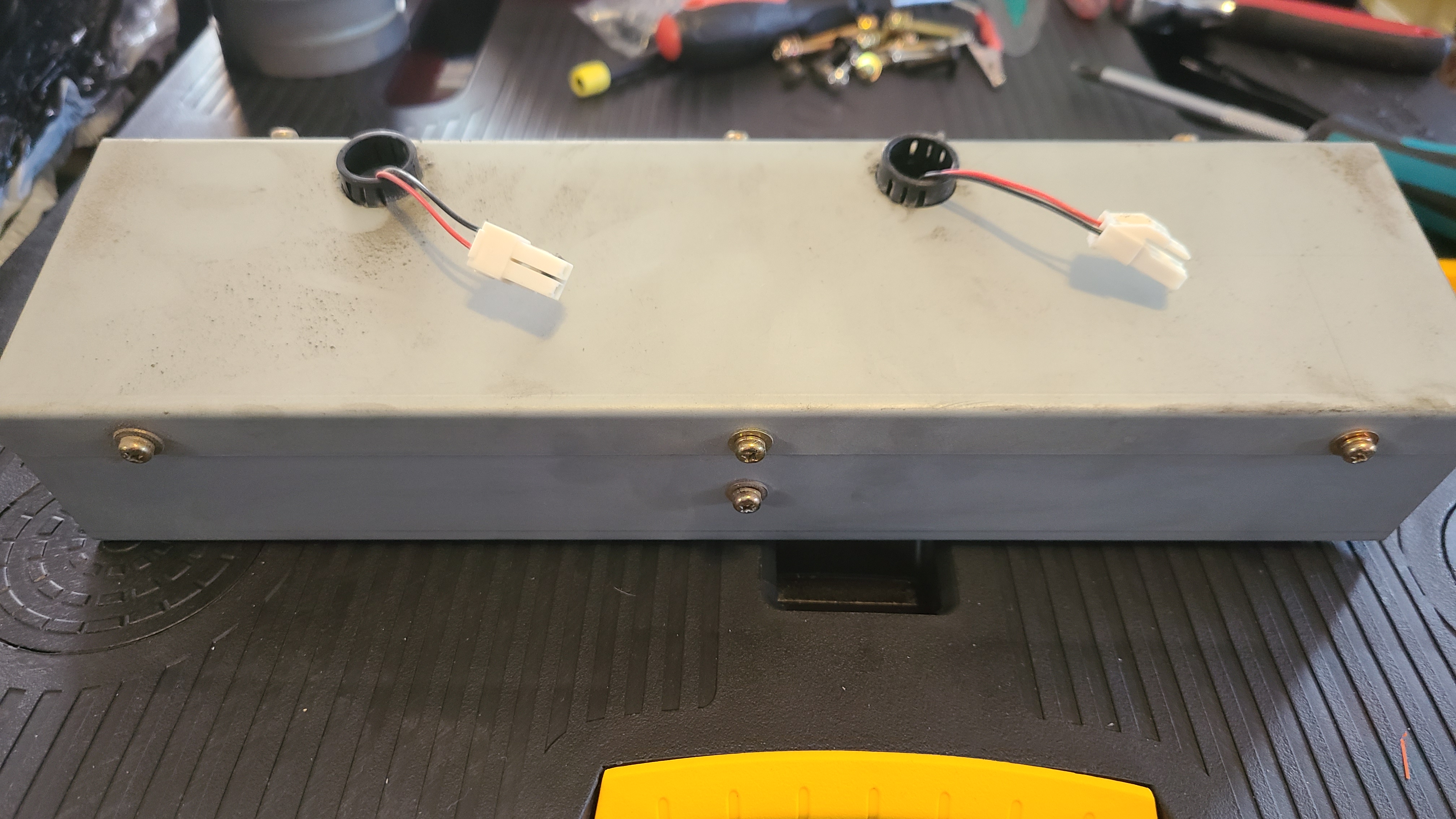
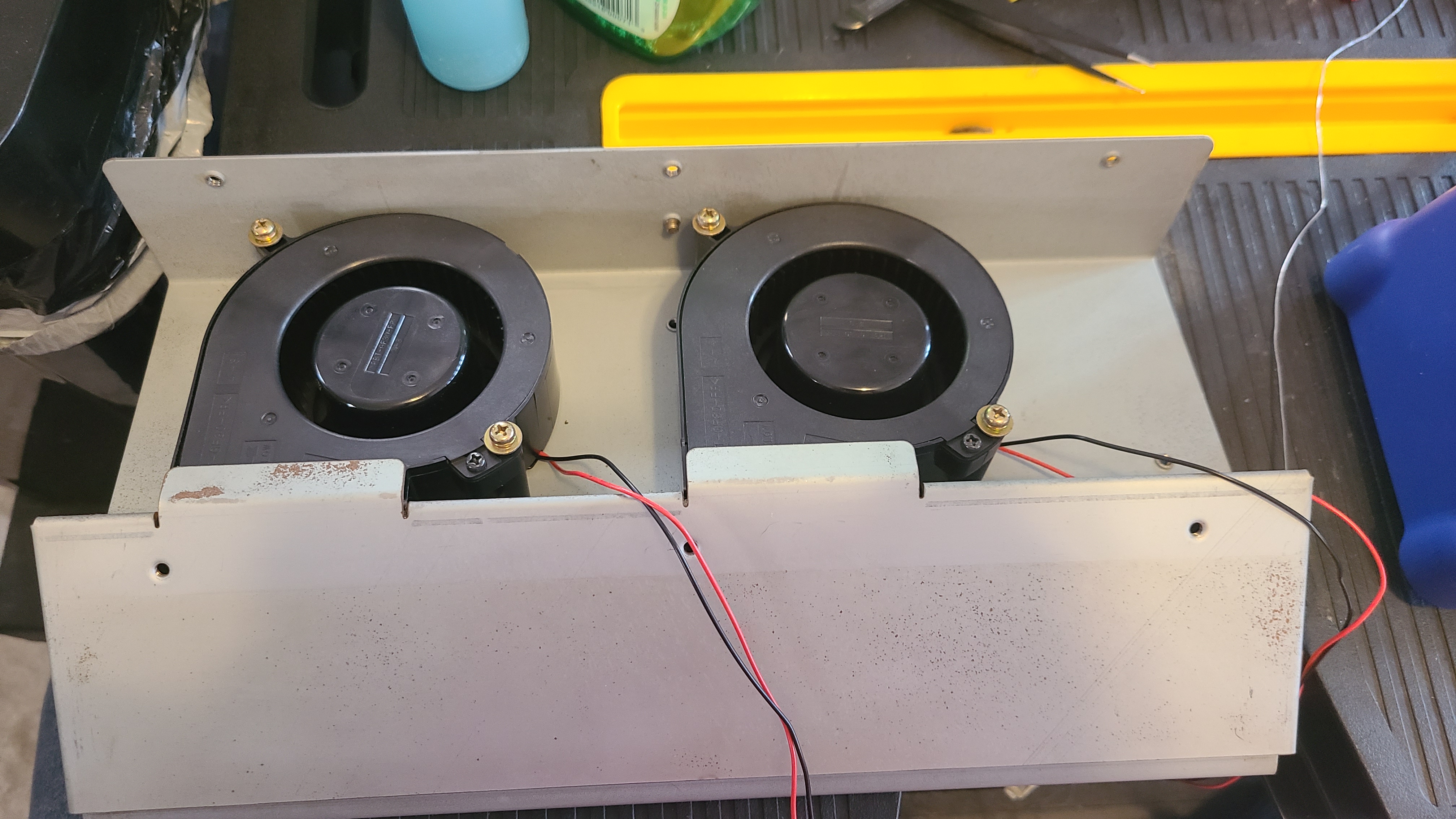
If you have disassembled the cab this far already, you may be interested in cleaning out the Blower Fans used to keep the screen cool and prevent yellowing over time. Reaching the Blower fans requires some significant disassembly, so it's often better to get all of this done in one shot, rather than reassemble the cab just to undo it all later when you do finally decide to clean the fans. 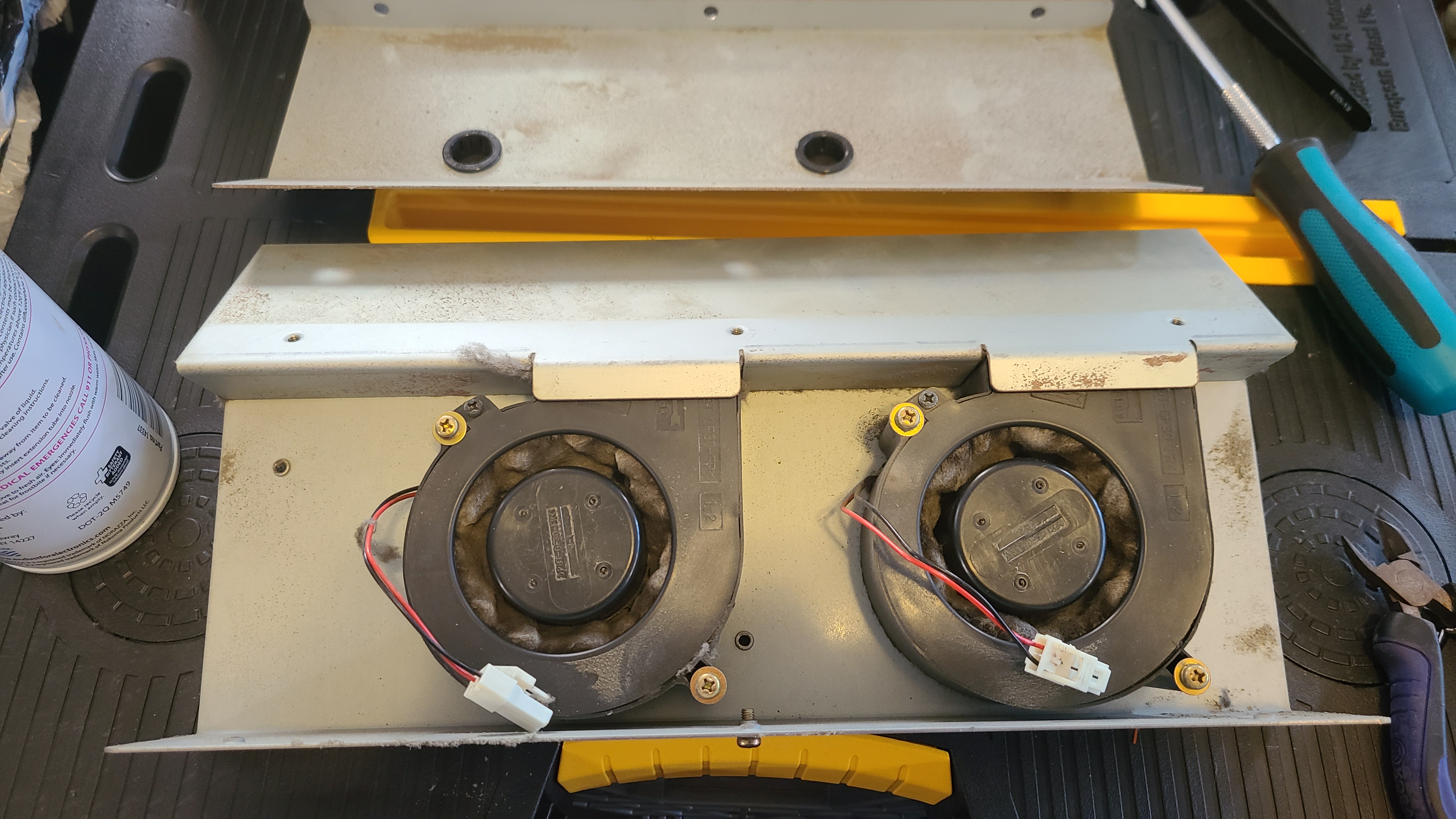 Pictured: Assembly opened; unserviced fans.
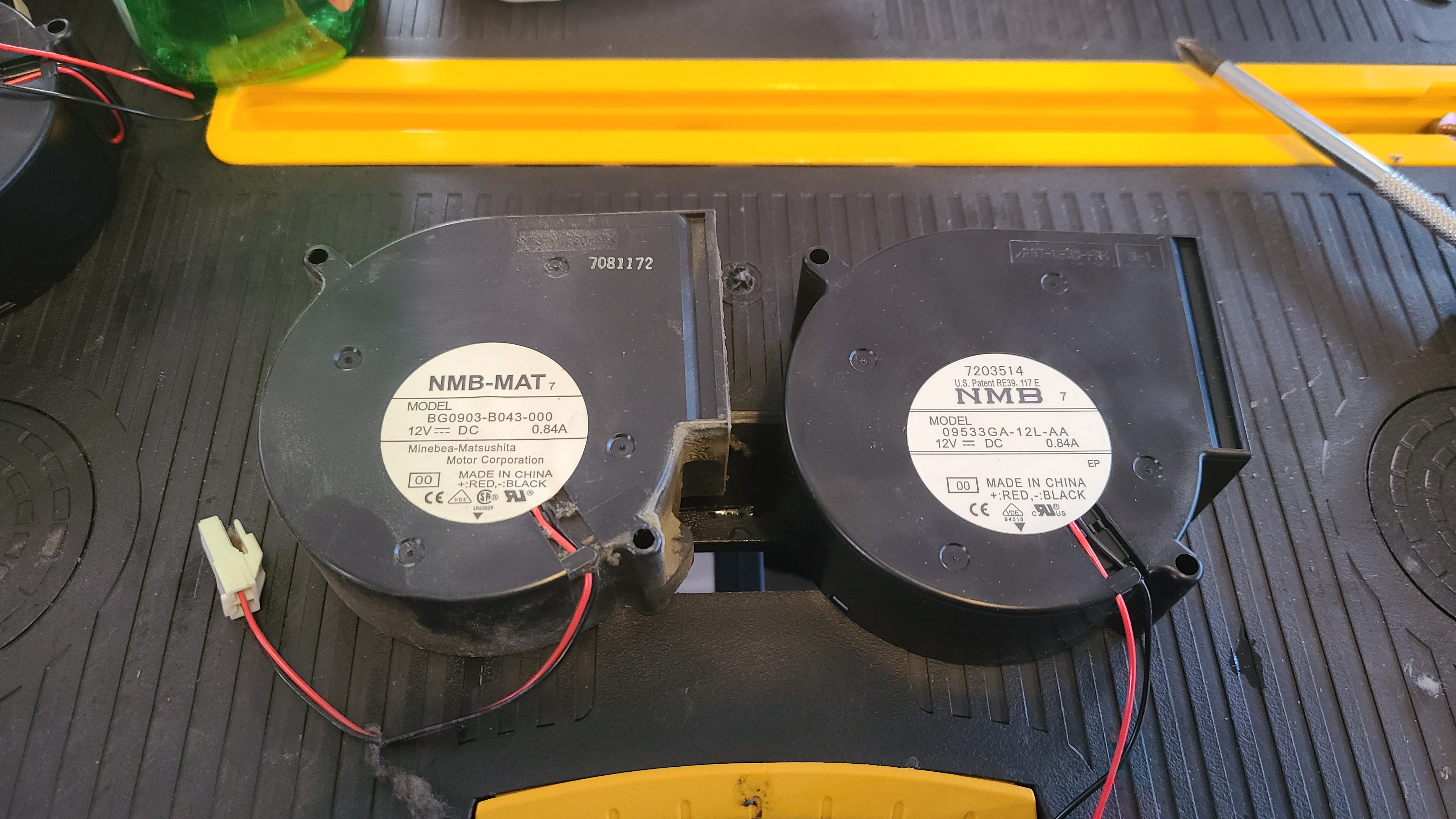 Pictured: Stock Blower - Left. New Blower - Right.The Blower fans have oftentimes never been serviced considering how laborious it can be to reach the assembly, so as these machines get older, this process falls ever closer into "mandatory" maintenance. The exact original blowers have long been discontinued, however, there is a factory-recommended replacement available: the 09533GA-12L-AA-00. Replacing the fans isn't necessarily required- the original fans are plenty sturdy and really just need a good once-through cleaning, though in case your fans are seriously borked or you just prefer having a fresh new pair, the option is available.
Pictured: Assembly opened; unserviced fans.Pictured: Stock Blower - Left. New Blower - Right.The Blower fans have oftentimes never been serviced considering how laborious it can be to reach the assembly, so as these machines get older, this process falls ever closer into "mandatory" maintenance. The exact original blowers have long been discontinued, however, there is a factory-recommended replacement available: the 09533GA-12L-AA-00. Replacing the fans isn't necessarily required- the original fans are plenty sturdy and really just need a good once-through cleaning, though in case your fans are seriously borked or you just prefer having a fresh new pair, the option is available.🔗 Continuing Disassembly: Removing the Monitor (Accessing Blower Assembly)
Our next step will be to take the monitor out. First, you are going to remove the large metal overlay surrounding the monitor. This is done by removing a few screws from both the Left and Right sides, as well as a singular screw that should have a ground lead. 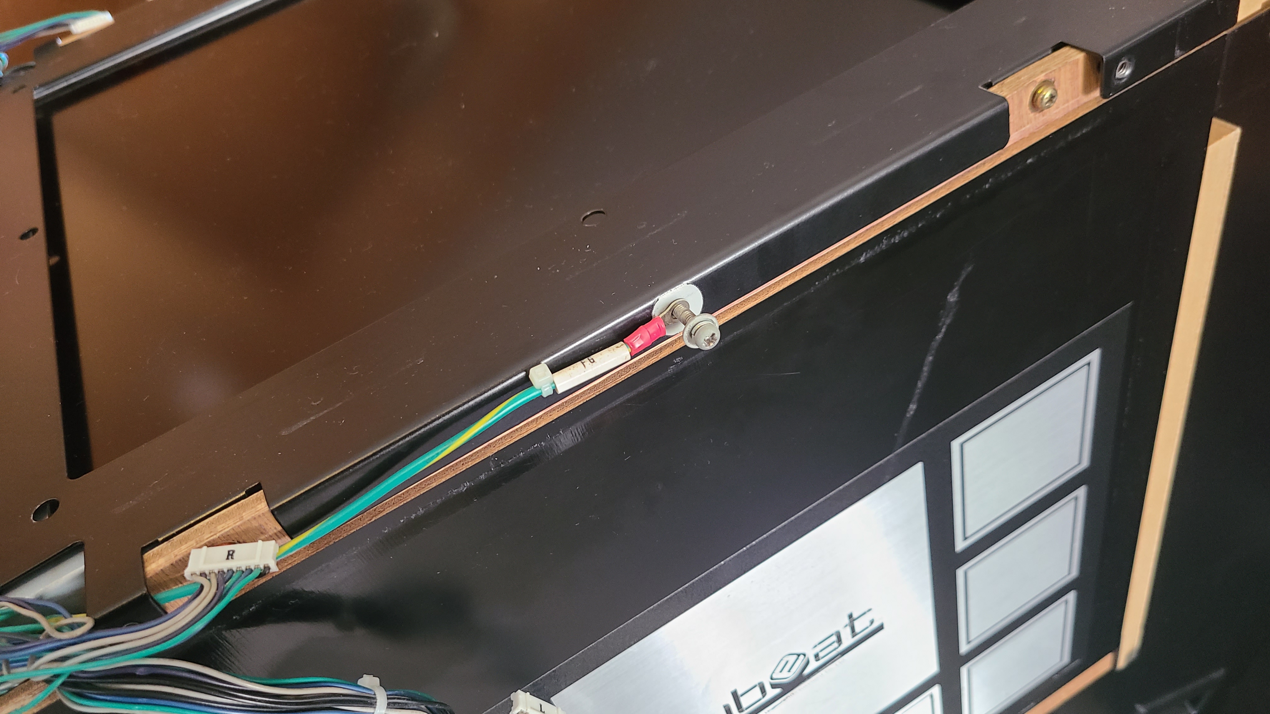
The monitor should now be rather bare.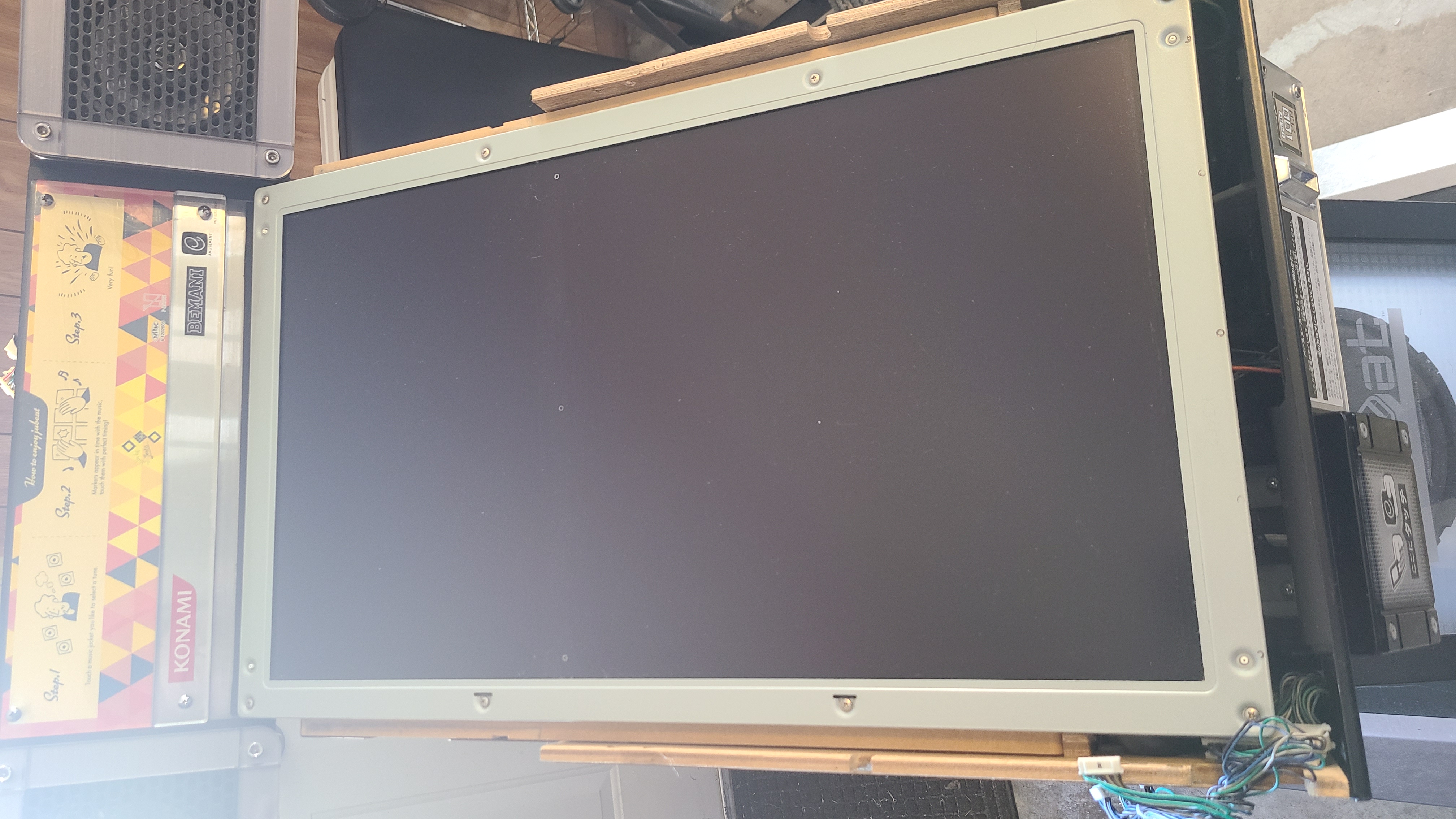 From here, you can simply get a good grip near the top of the monitor and lean forwards towards the front of the game to stand it up on its leftmost/bottom side. Be careful, however: there are a few cables connected to the backside of the monitor that need to be taken out, so don't go yanking it out all the way just yet.
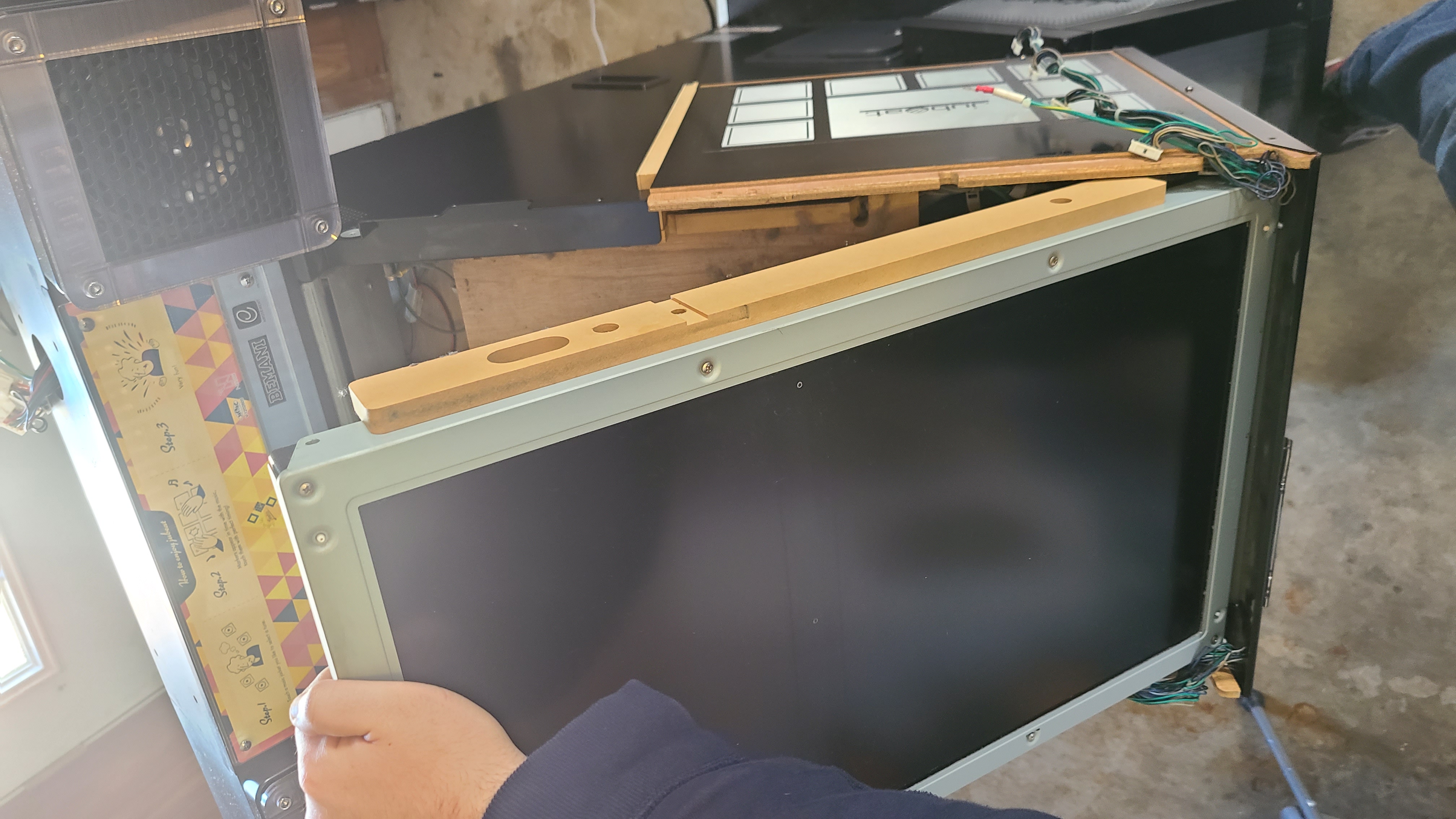 Being careful not to pull at the few monitor cables...
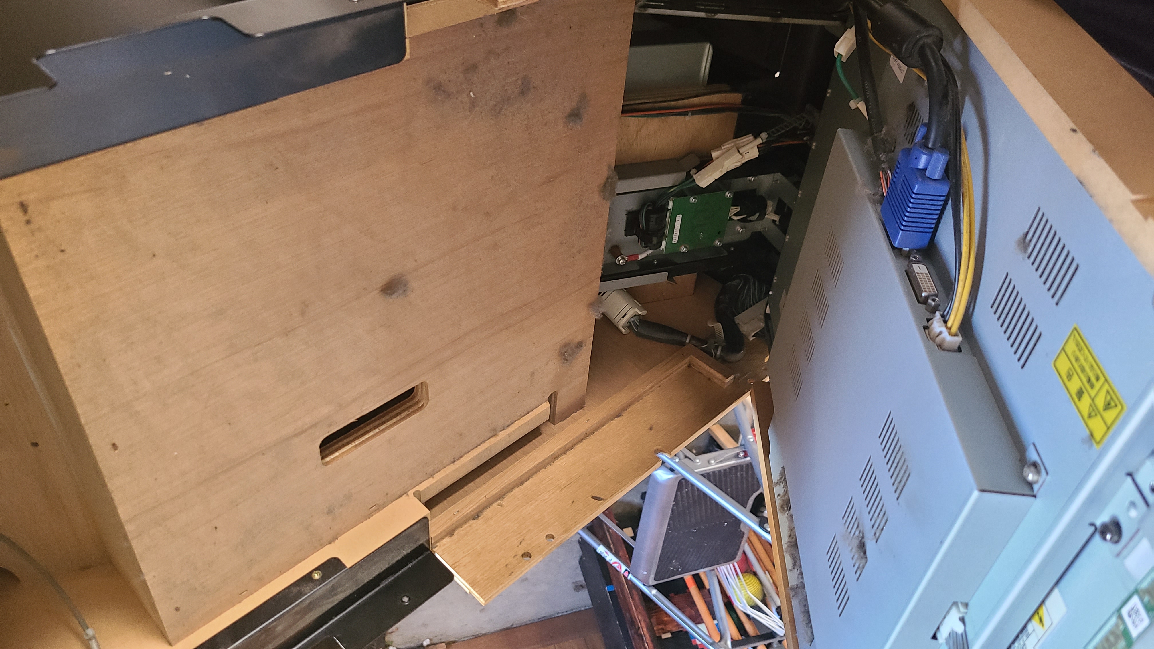 There should be four in total. Three leading into the monitor and one additional ground pin screwed into the frame (you can just disconnect this and leave the small end screwed in). Afterward, the monitor can then be lifted up and out and placed elsewhere for now. Take this opportunity to access the card reader if need be, as well as cleanout any ancient dust bunnies you most certainly have hiding out in there.
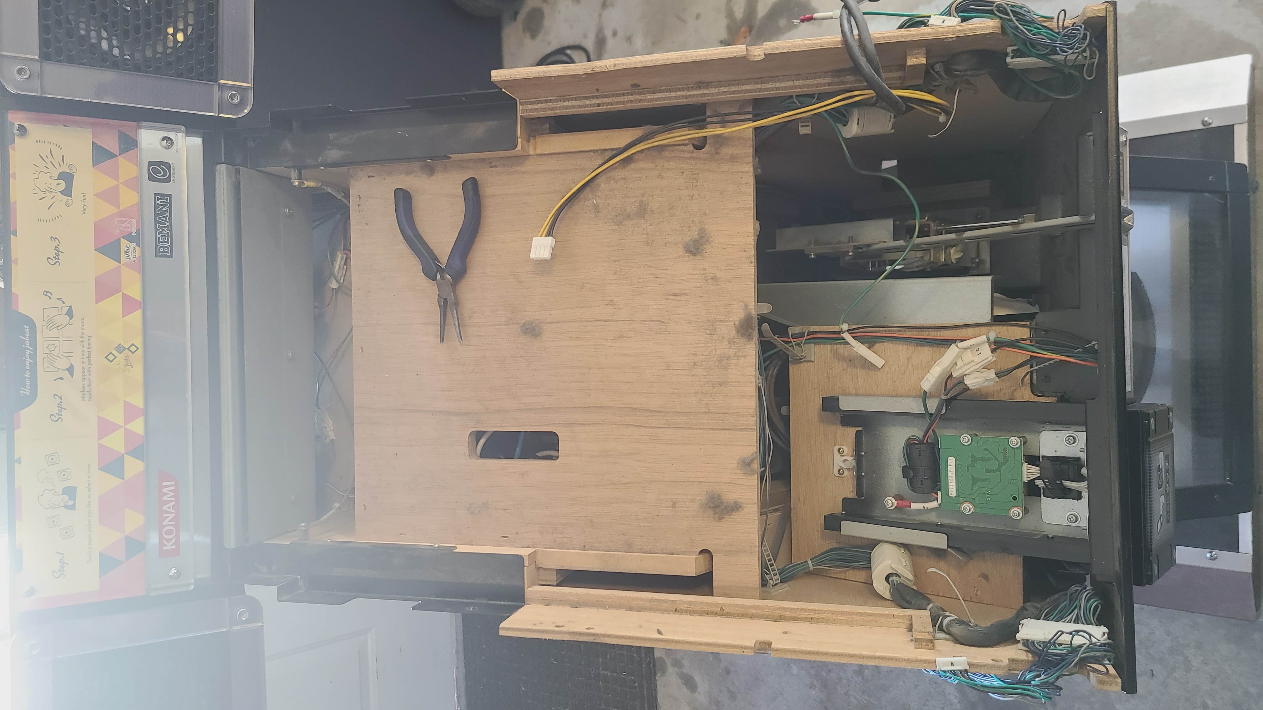 From here, you can also finally get a good look at where the Blower Assembly is located; seen just below the instruction marquee. Unfortunately, we're not quite done. The next step will be to remove this wing-span piece that houses both speakers.
The monitor should now be rather bare.
From here, you can simply get a good grip near the top of the monitor and lean forwards towards the front of the game to stand it up on its leftmost/bottom side. Be careful, however: there are a few cables connected to the backside of the monitor that need to be taken out, so don't go yanking it out all the way just yet.Being careful not to pull at the few monitor cables...There should be four in total. Three leading into the monitor and one additional ground pin screwed into the frame (you can just disconnect this and leave the small end screwed in). Afterward, the monitor can then be lifted up and out and placed elsewhere for now. Take this opportunity to access the card reader if need be, as well as cleanout any ancient dust bunnies you most certainly have hiding out in there.From here, you can also finally get a good look at where the Blower Assembly is located; seen just below the instruction marquee. Unfortunately, we're not quite done. The next step will be to remove this wing-span piece that houses both speakers.🔗 Quick aside: Removing the Cube and Monitor Cleaning
Removing the speaker housing will require removing the top Cube, but this is pretty obviously done. Remove the top back panel, disconnect the four connectors inside leading into the cube, undo the four hex bolts from the left and right sides of the cube and lift away. Inside the cube base there will be four screws- simply remove those and the small wooden triangular base will come away from the speaker housing. Fill ethereal cube with stuffed animals to your heart's content before reassembly.
Also, you may want to take this opportunity to give the monitor a little cleaning. Not much needs to be done: disconnect the leftmost harness from the left side, then remove the circled screws.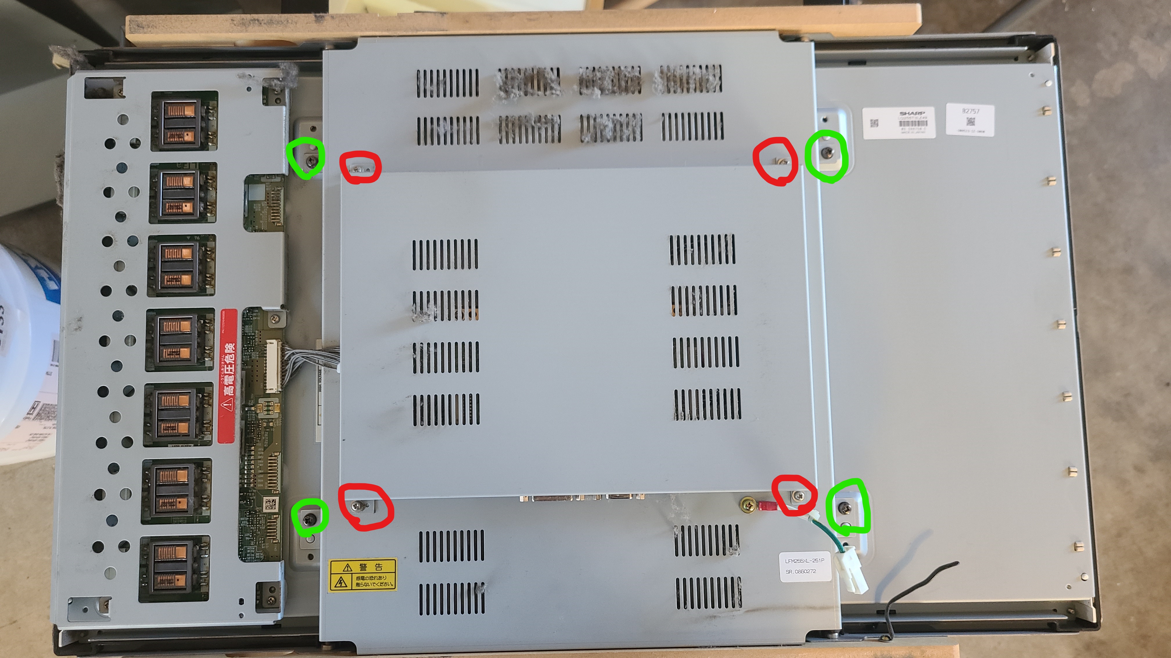 The top shield can be removed first and cleaned separately, then you will see the many wires connecting the input board to the back of the monitor inside some plastic cable holders. Gingerly take the wires out of the cable holders to relieve strain, then GENTLY lean the larger piece up from the bottom to clean it out from underneath. You can disconnect this harness if you would like to clean it further, though simply leaning it back and dusting this way is more than serviceable. This is where the bulk of the clumped-up dust is going to be sitting, so only disconnecting it this far is fine. Once cleaned, reseat the shields, mount, reconnect the leftmost harness and finish the disassembly/reassembly of the cab.
Also, you may want to take this opportunity to give the monitor a little cleaning. Not much needs to be done: disconnect the leftmost harness from the left side, then remove the circled screws.
The top shield can be removed first and cleaned separately, then you will see the many wires connecting the input board to the back of the monitor inside some plastic cable holders. Gingerly take the wires out of the cable holders to relieve strain, then GENTLY lean the larger piece up from the bottom to clean it out from underneath. You can disconnect this harness if you would like to clean it further, though simply leaning it back and dusting this way is more than serviceable. This is where the bulk of the clumped-up dust is going to be sitting, so only disconnecting it this far is fine. Once cleaned, reseat the shields, mount, reconnect the leftmost harness and finish the disassembly/reassembly of the cab.🔗 Removing the Speaker Housing (Accessing Blower Assembly)
You can tackle a few things here in whatever order really, but getting the speaker housing to finally lift away can be a little tedious. May as well get the most laborious thing out of the way: First, you're going to want to remove the back fan panel. There are a few Phillips heads holding the smaller shield on if you would like to remove that, then a number of surrounding hex screws holding the fan plate onto the back of the cabinet. Remove these to expose the fan harnesses and more interior screws. 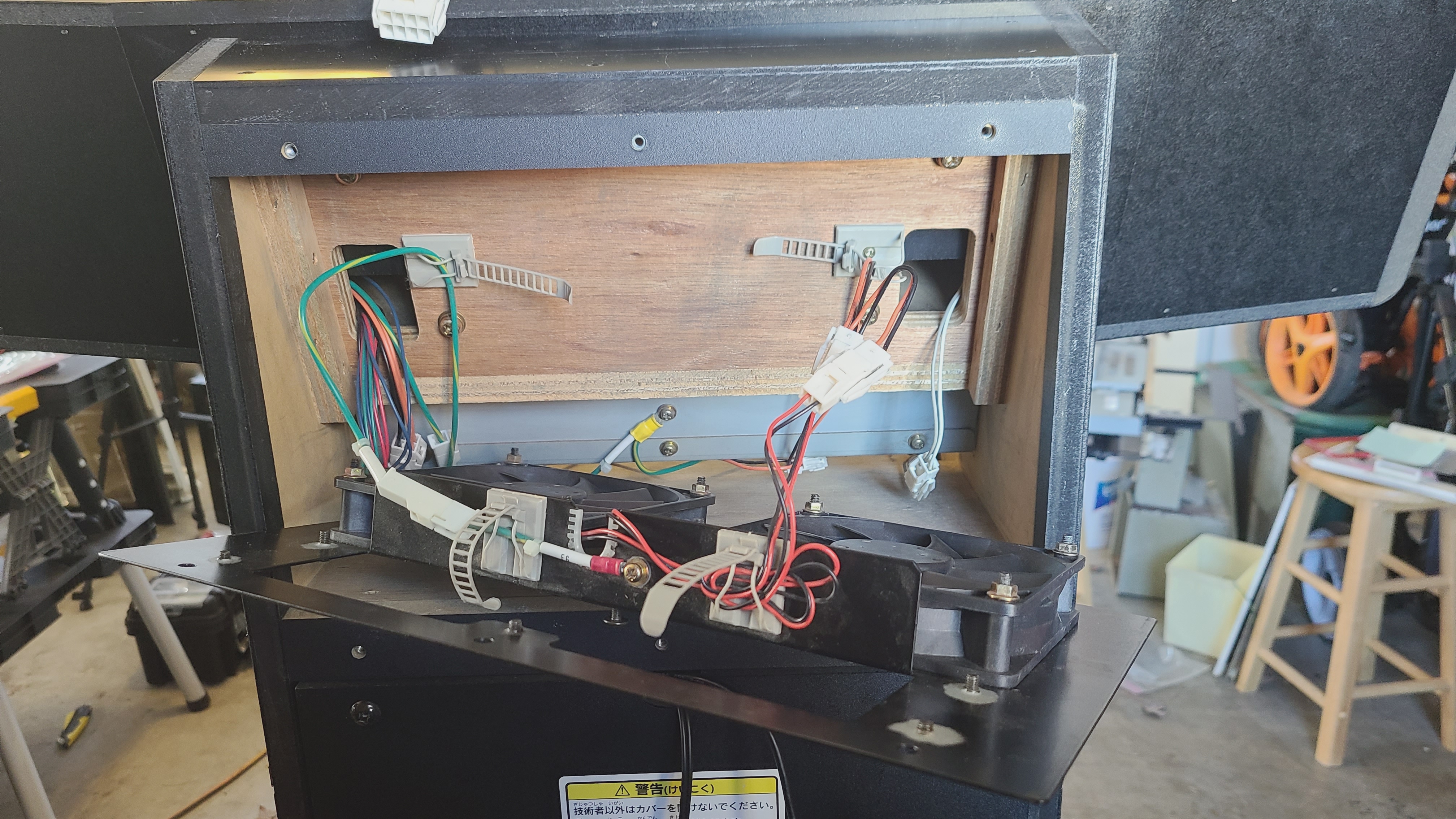 There are a number of things to disconnect here:
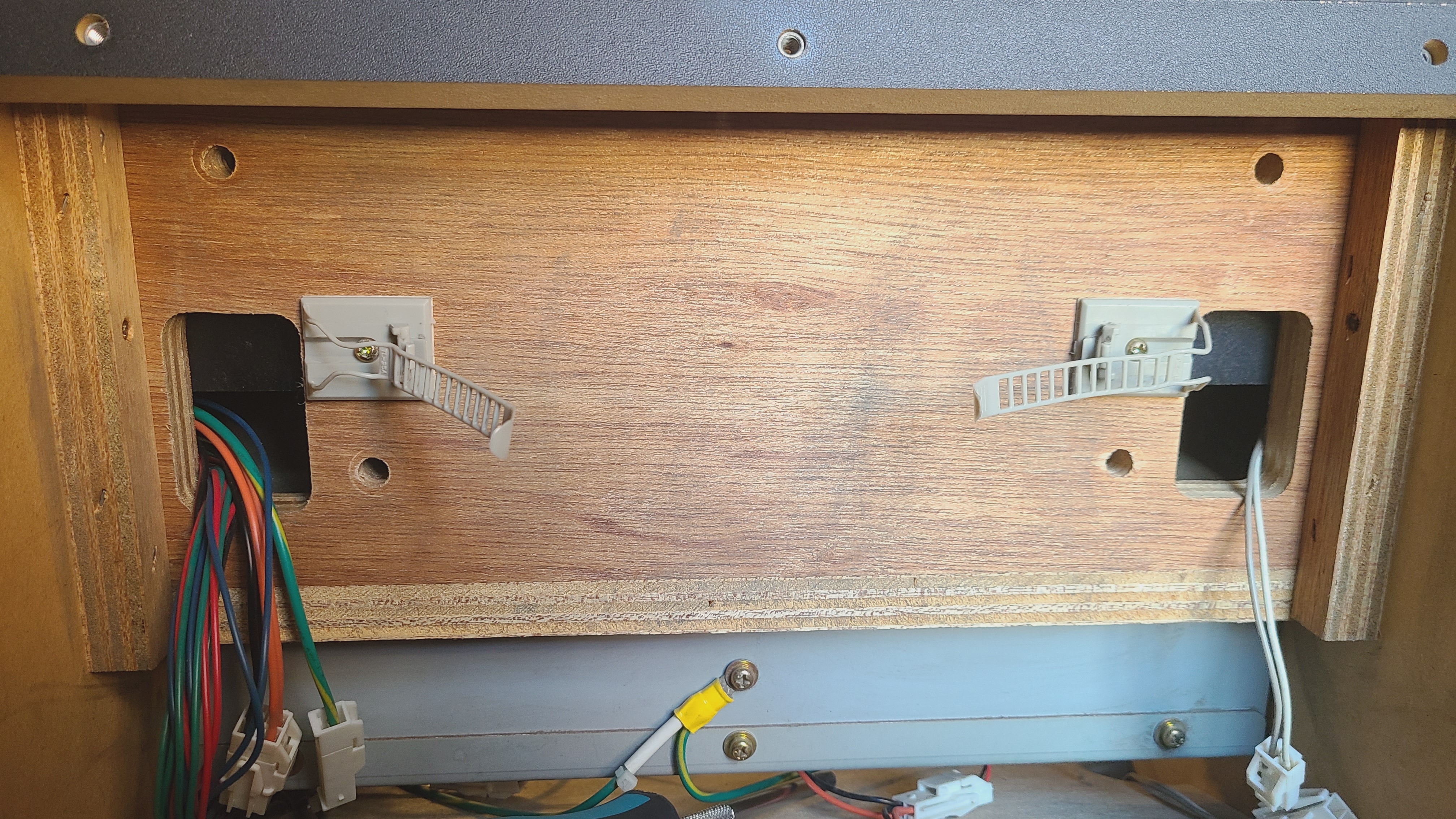 Afterward, be sure to remove the two screws located underneath each speaker's lower plate. Only the two screws connected to the housing needs to be removed:
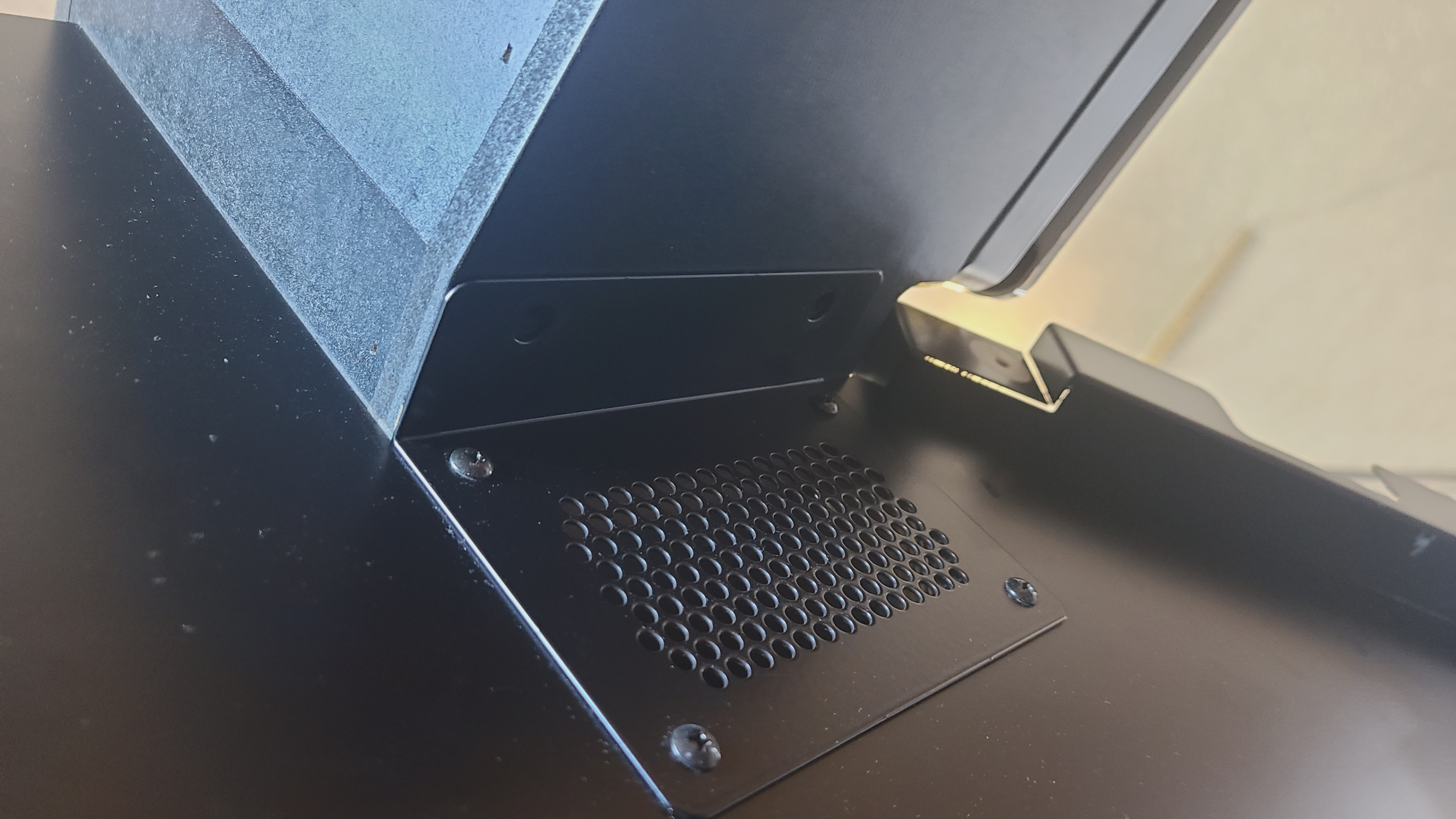 Finally, you may have noticed that you can't pull the harness that was leading up into the cube through the back. This is because there is another cable holder hidden inside the speaker assembly that is rather annoying to get to. The easiest way to access it is to remove the Rightmost speaker. There are four hex bolts holding the frame in place (Be careful to catch the clear plastic rings between the frame and the housing!) and then a few screws holding the speaker onto the housing itself. Remove the speaker and you can see where the harness is being held in place:
 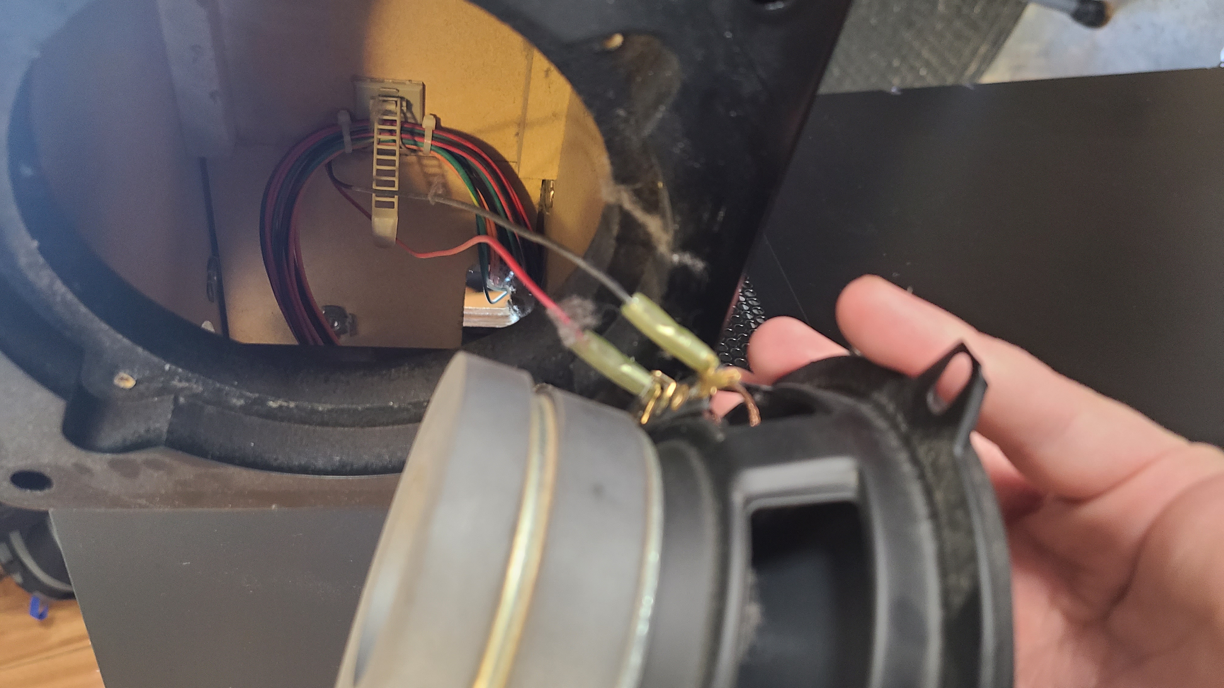 Once the harness is freed and pulled through the back, the speaker housing should now be free, and can safely be lifted up and placed off to the side. Finally, we can unmount the Blower Fan Assembly!
There are a number of things to disconnect here:- Both fan connectors
- Ground for fans
- Left speaker harness (pictured here on the right)
- Unscrew ground from Blower Fan Assembly
Afterward, be sure to remove the two screws located underneath each speaker's lower plate. Only the two screws connected to the housing needs to be removed:Finally, you may have noticed that you can't pull the harness that was leading up into the cube through the back. This is because there is another cable holder hidden inside the speaker assembly that is rather annoying to get to. The easiest way to access it is to remove the Rightmost speaker. There are four hex bolts holding the frame in place (Be careful to catch the clear plastic rings between the frame and the housing!) and then a few screws holding the speaker onto the housing itself. Remove the speaker and you can see where the harness is being held in place: Once the harness is freed and pulled through the back, the speaker housing should now be free, and can safely be lifted up and placed off to the side. Finally, we can unmount the Blower Fan Assembly!🔗 Accessing and Cleaning/Replacing the Blower Assembly
You should now be able to see the three screws holding the Assembly in place. 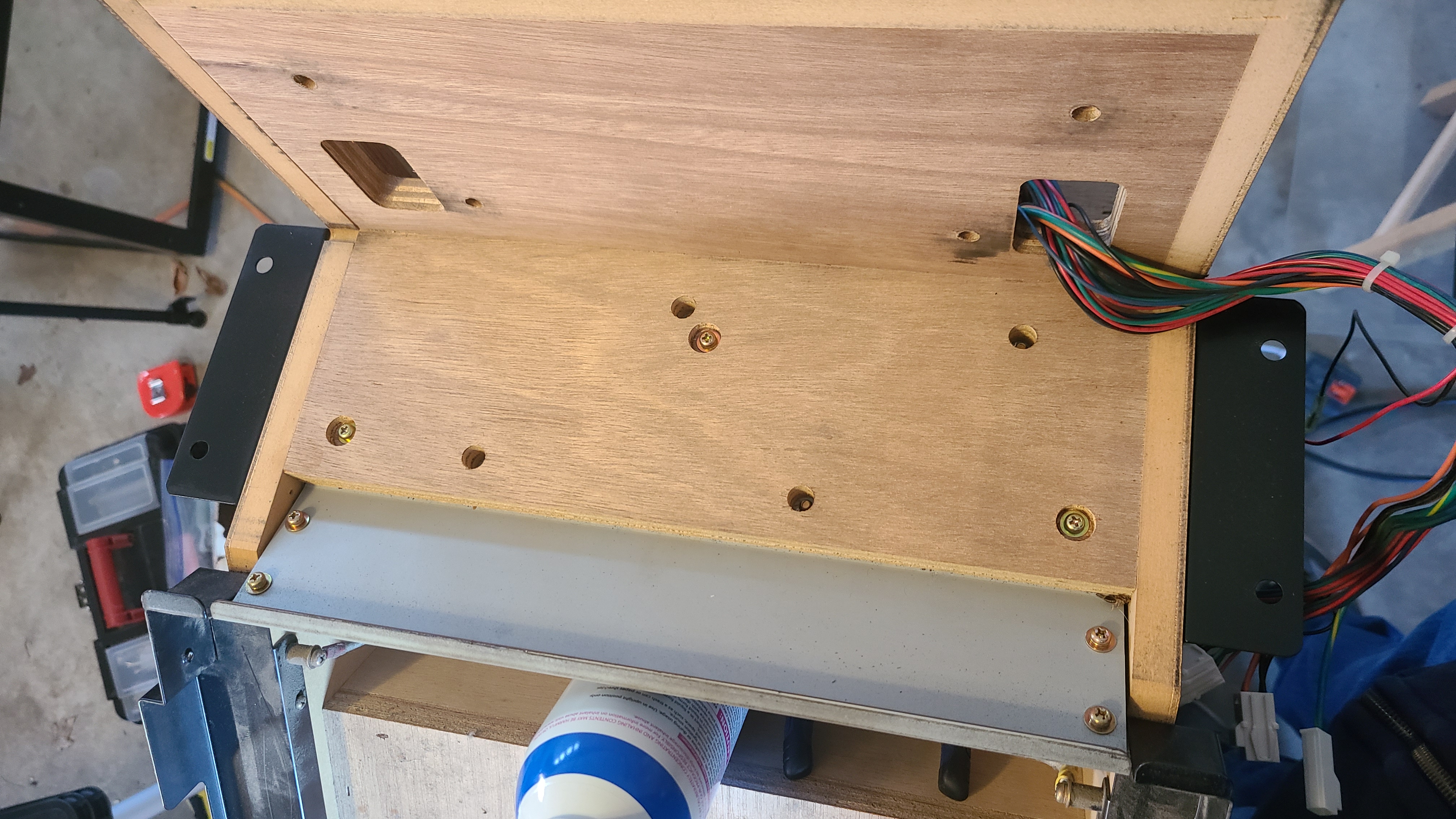 Remove them, and assuming you disconnected the ground screw from the back listed in the previous steps, you should be able to slide the assembly towards the front of the game, then up and out. It's a snug fit, but it should slide out just fine without damaging anything with a little elbow grease.
 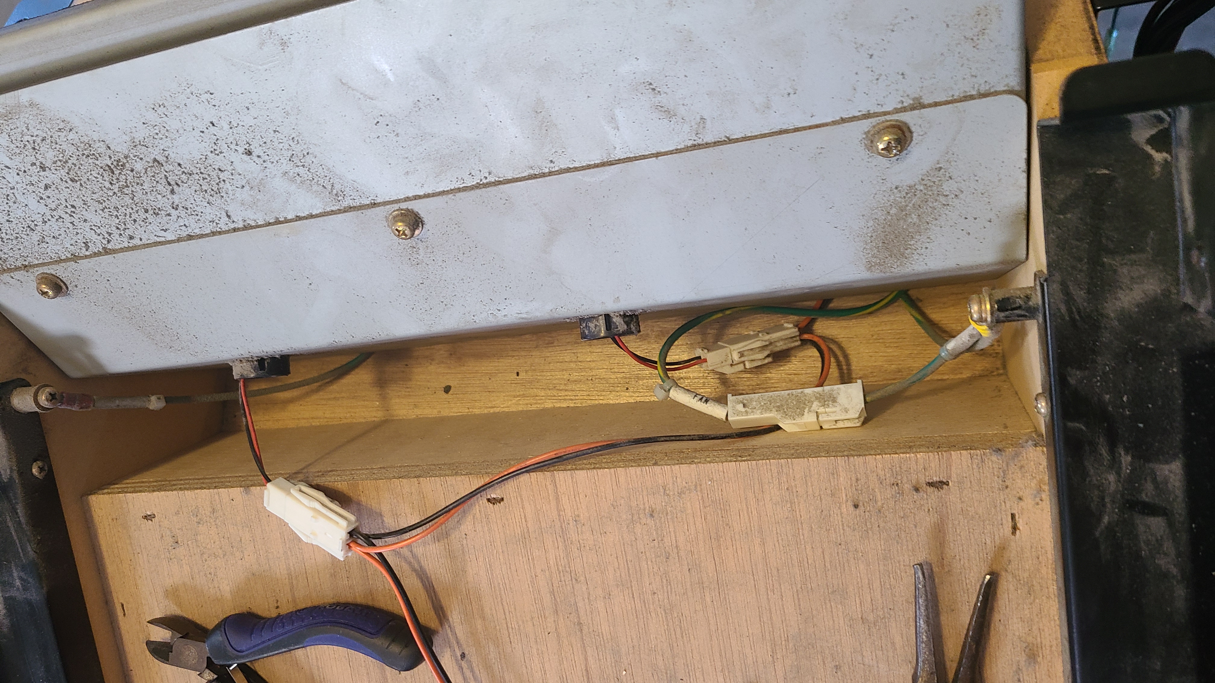 It's pretty self-explanatory from here, thankfully. Remove the screws on both the front and back of the assembly to remove the top panel.
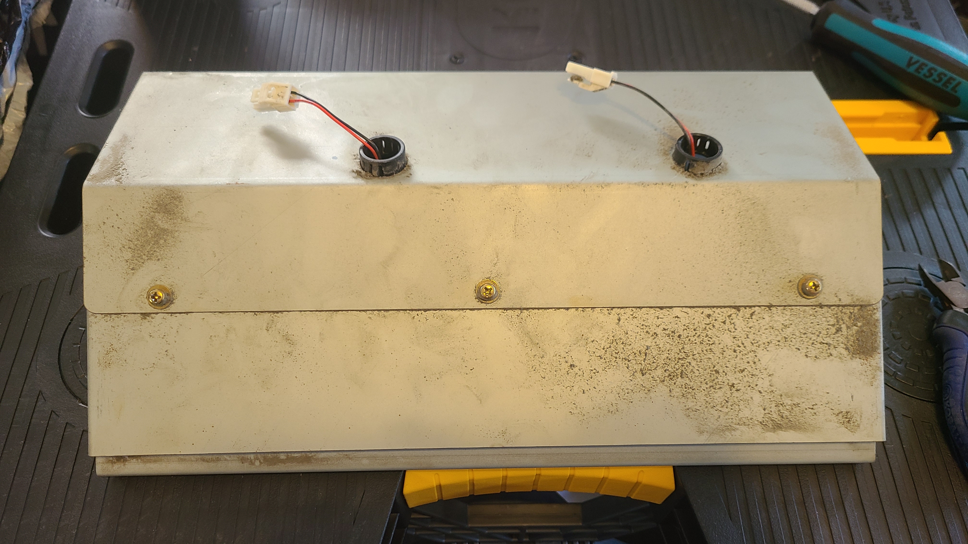
There are two screws mounting each fan in place, then one smaller screw keeping the top lid held in place. Remove all of these to both free the fans from the assembly and remove the top lid of the fan. From here, I recommend using some blunt-ended forceps to get between the edges of the fan blades and take out everything that you can. Remove as much debris as possible, hit it with a little canned air, repeat. Take a vacuum to it if that makes you feel good. (Fair warning, the next couple images may not be all that fun to look at for some. It's dirty work; that's the reality :shrug:)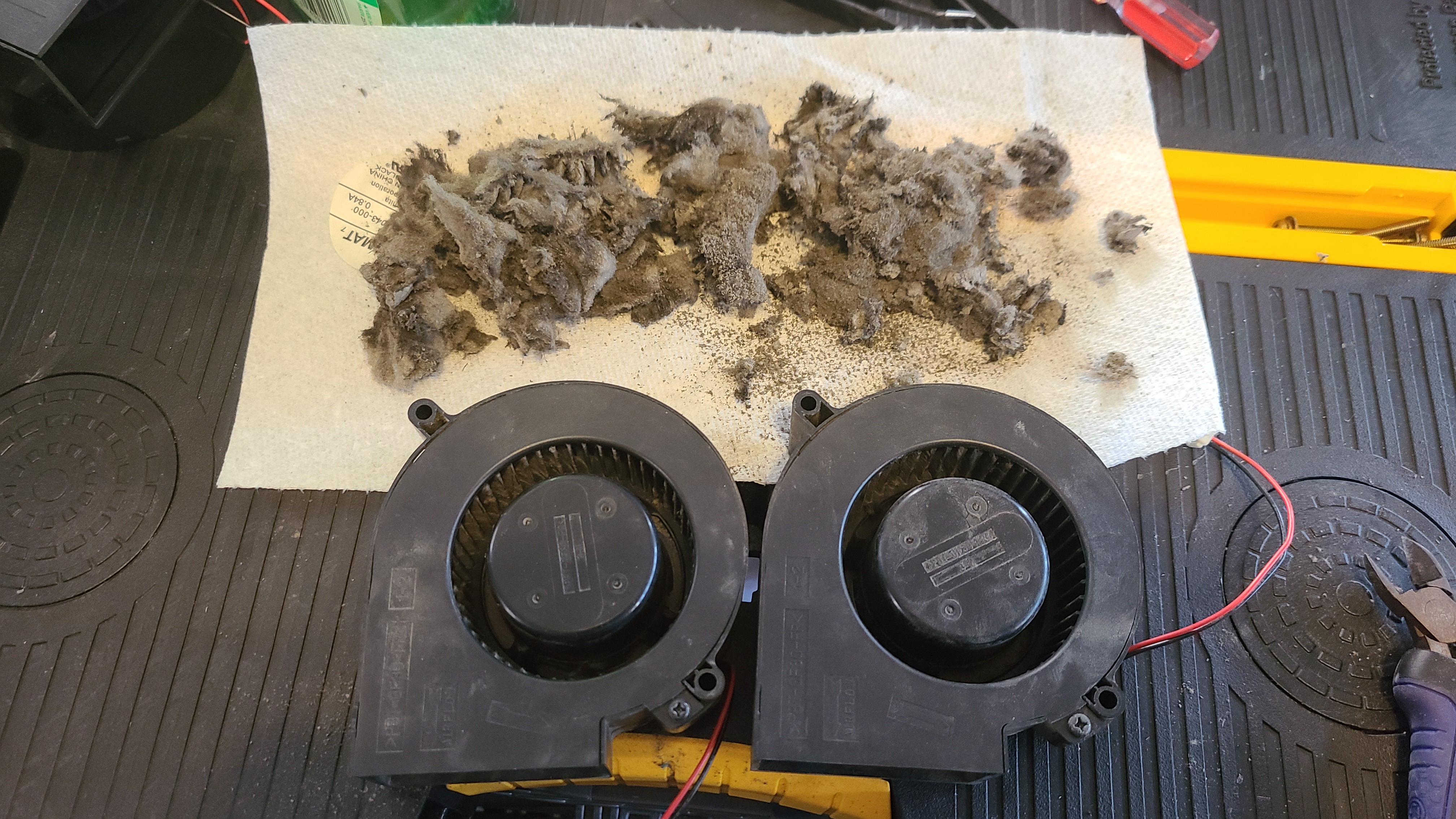
This image is just an example really, but it is possible to take the blower out of place to clean further by removing the small clip on the opposite side of the fan. DO NOT DO THIS unless you really have to. That clip is incredibly small, finicky, and an absolute pain to put back on. You can clean the fan just fine without removing it like this.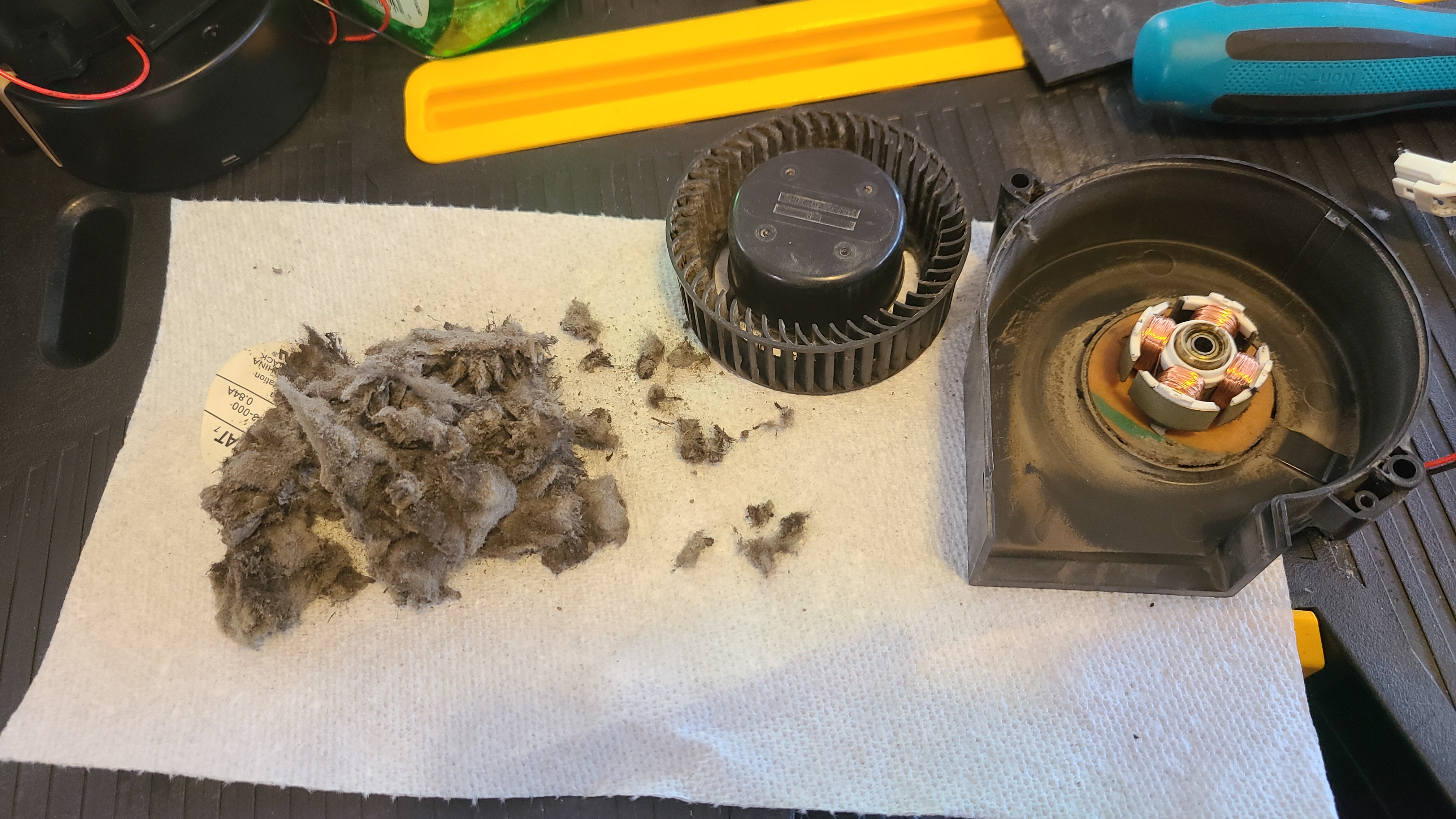
Finally, if you've purchased some, you can snip off the connectors from the old fans and solder them onto the new replacement fans before reassembly. If you didn't get replacements, then simply finish cleaning and remount the fans back into the assembly.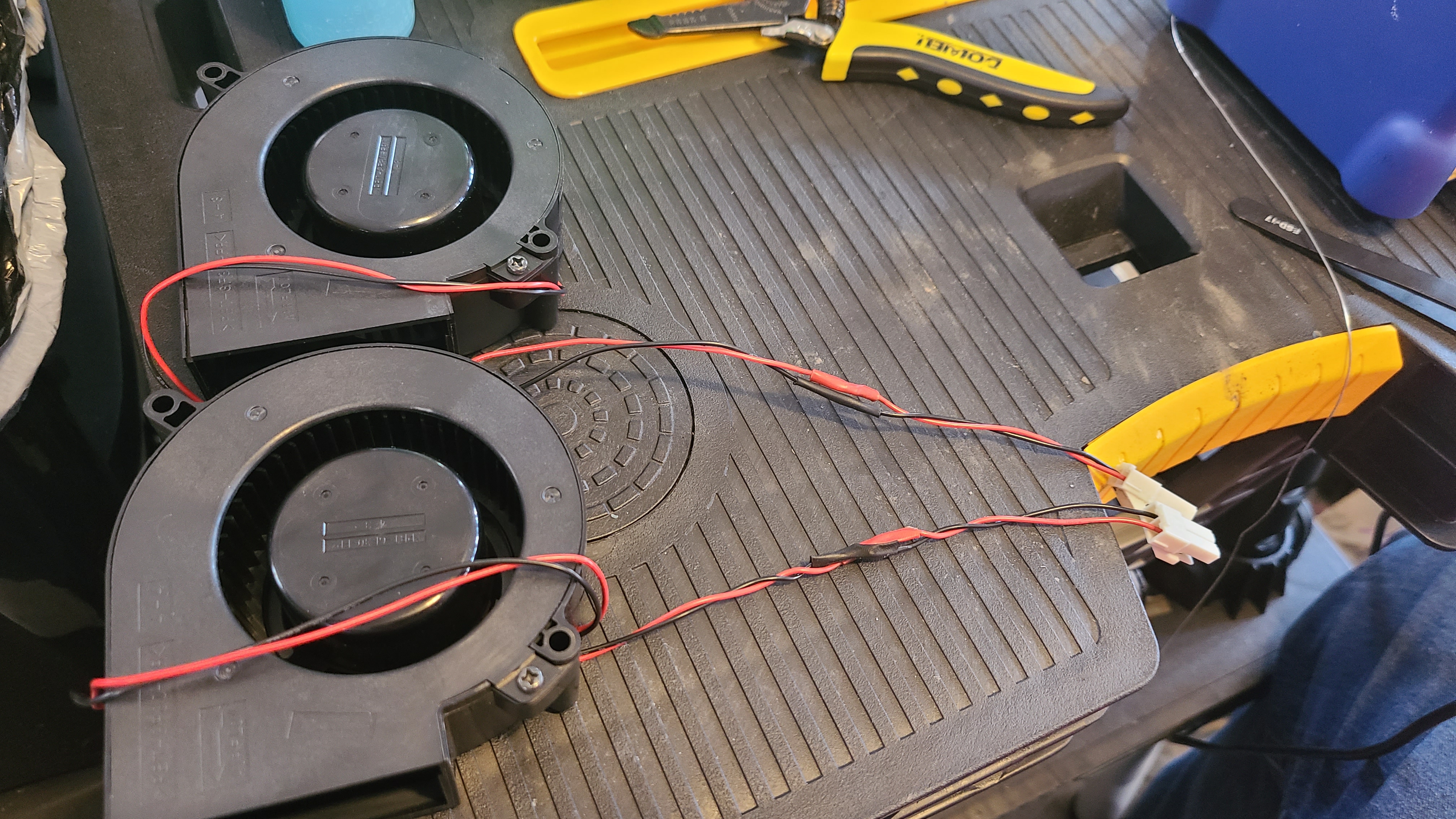
 and you're done! Before beginning reassembly completely, you can plug in the blower fans and power on the cabinet while everything else is still disconnected just to test that they are in fact blowing properly. Once you've confirmed that they're good to go, simply follow this guide in reverse to reassemble. Hopefully, you've been keeping good track of your screws ^^
Remove them, and assuming you disconnected the ground screw from the back listed in the previous steps, you should be able to slide the assembly towards the front of the game, then up and out. It's a snug fit, but it should slide out just fine without damaging anything with a little elbow grease. It's pretty self-explanatory from here, thankfully. Remove the screws on both the front and back of the assembly to remove the top panel.There are two screws mounting each fan in place, then one smaller screw keeping the top lid held in place. Remove all of these to both free the fans from the assembly and remove the top lid of the fan. From here, I recommend using some blunt-ended forceps to get between the edges of the fan blades and take out everything that you can. Remove as much debris as possible, hit it with a little canned air, repeat. Take a vacuum to it if that makes you feel good. (Fair warning, the next couple images may not be all that fun to look at for some. It's dirty work; that's the reality :shrug:)This image is just an example really, but it is possible to take the blower out of place to clean further by removing the small clip on the opposite side of the fan. DO NOT DO THIS unless you really have to. That clip is incredibly small, finicky, and an absolute pain to put back on. You can clean the fan just fine without removing it like this.
Finally, if you've purchased some, you can snip off the connectors from the old fans and solder them onto the new replacement fans before reassembly. If you didn't get replacements, then simply finish cleaning and remount the fans back into the assembly.
and you're done! Before beginning reassembly completely, you can plug in the blower fans and power on the cabinet while everything else is still disconnected just to test that they are in fact blowing properly. Once you've confirmed that they're good to go, simply follow this guide in reverse to reassemble. Hopefully, you've been keeping good track of your screws ^^🔗 Speaker replacement
The factory speakers in Jubeat are great. However, as time passes, their membrane will start to degrade and eventually fall off. This will obviously cause a major sound quality decrease, and you might start hearing weird buzzing noises here and there. When that happens, you have two options: Either take the time to refoam the membranes (you can look up for "Refoaming Kits" online) or buy new speakers altogether.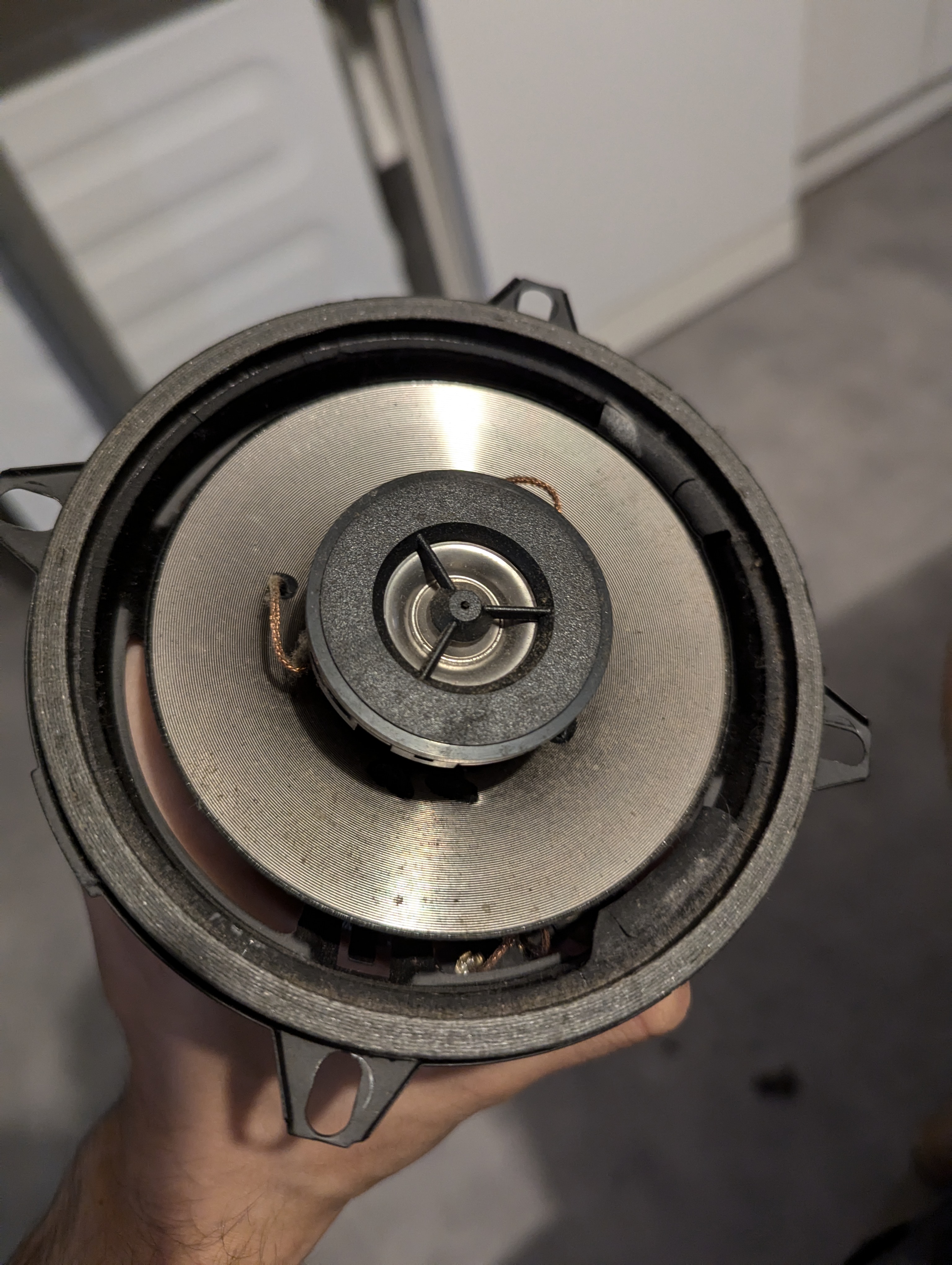 Who hurt you ?!
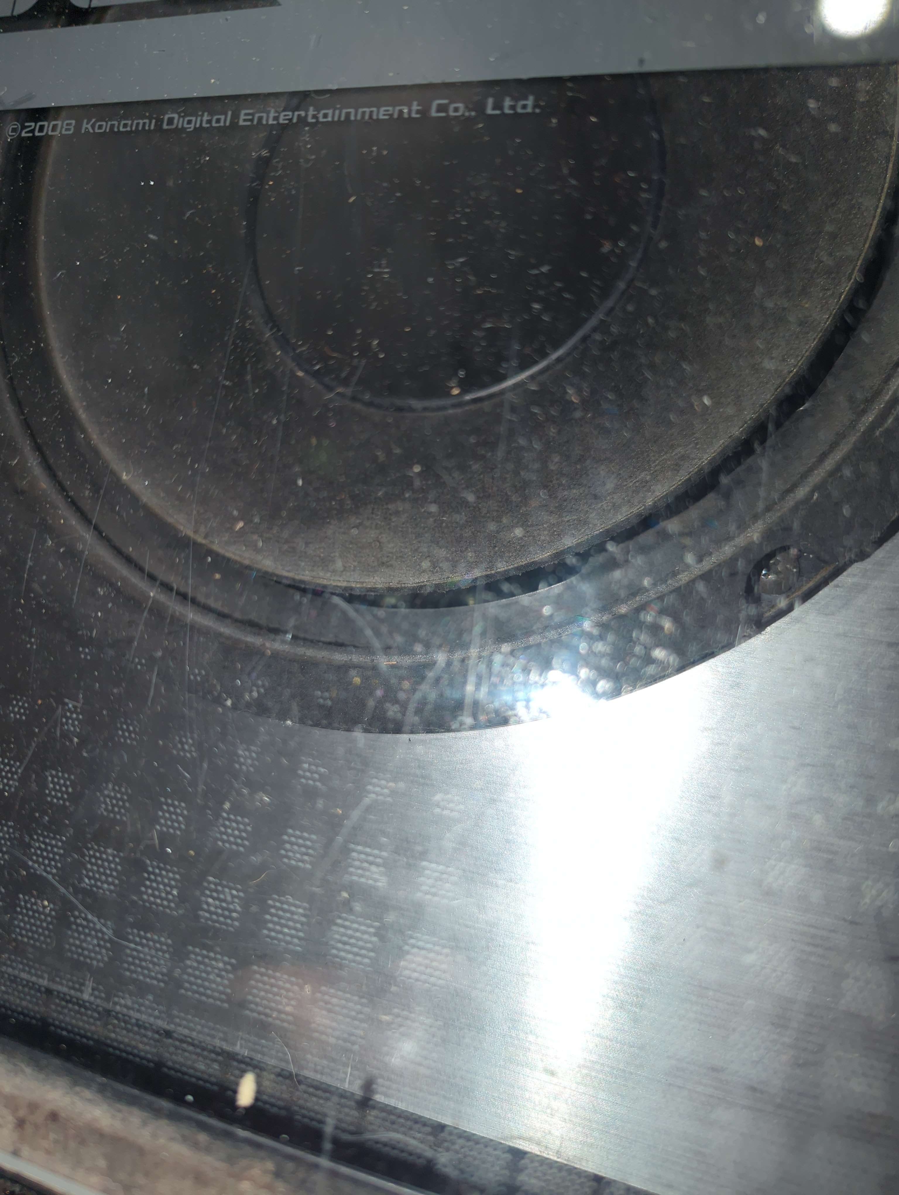 Removing the speakers is rather easy, you will first need to remove the 4 screws from their cover
 Be careful not to drop the acrylic spacers that go at the back of the assembly
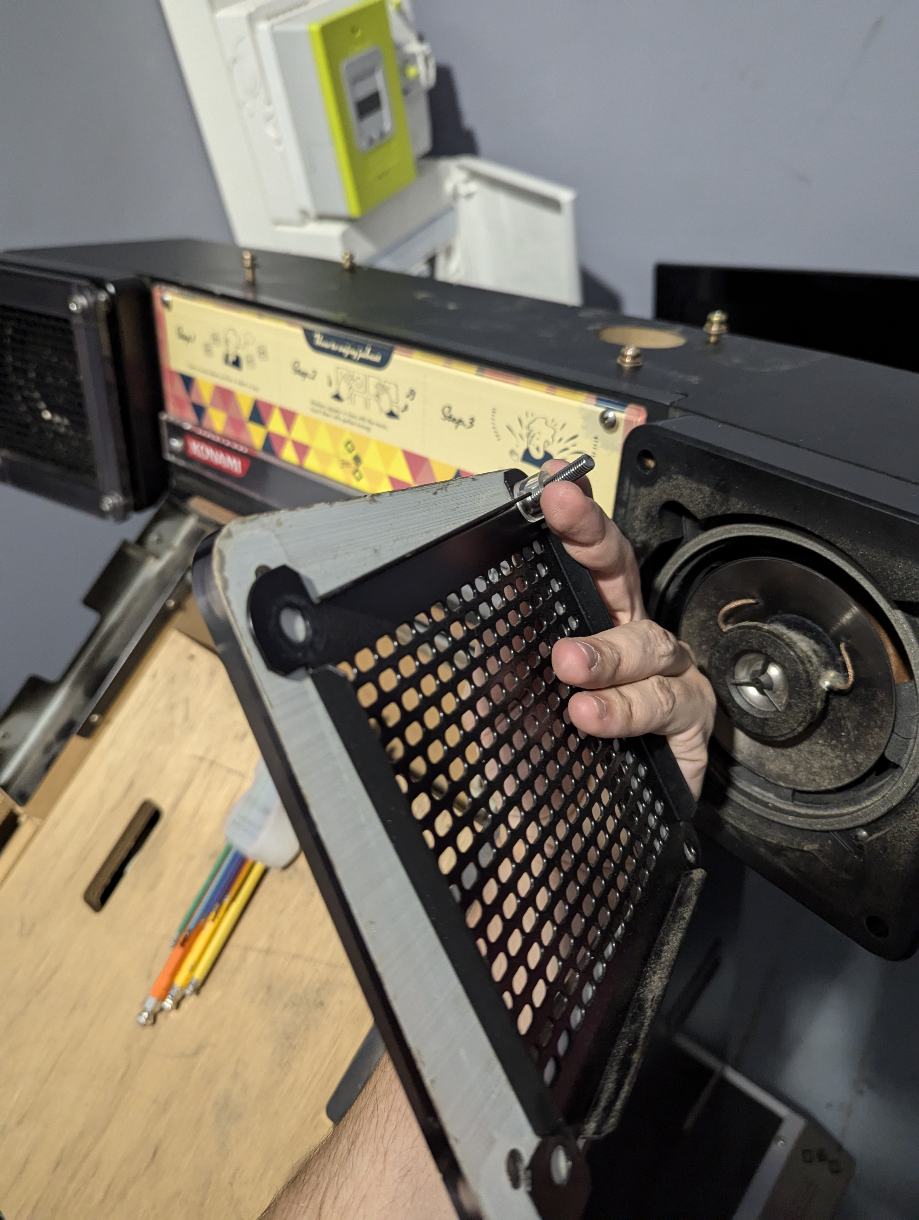 Then remove the 4 screws that hold the speaker in place
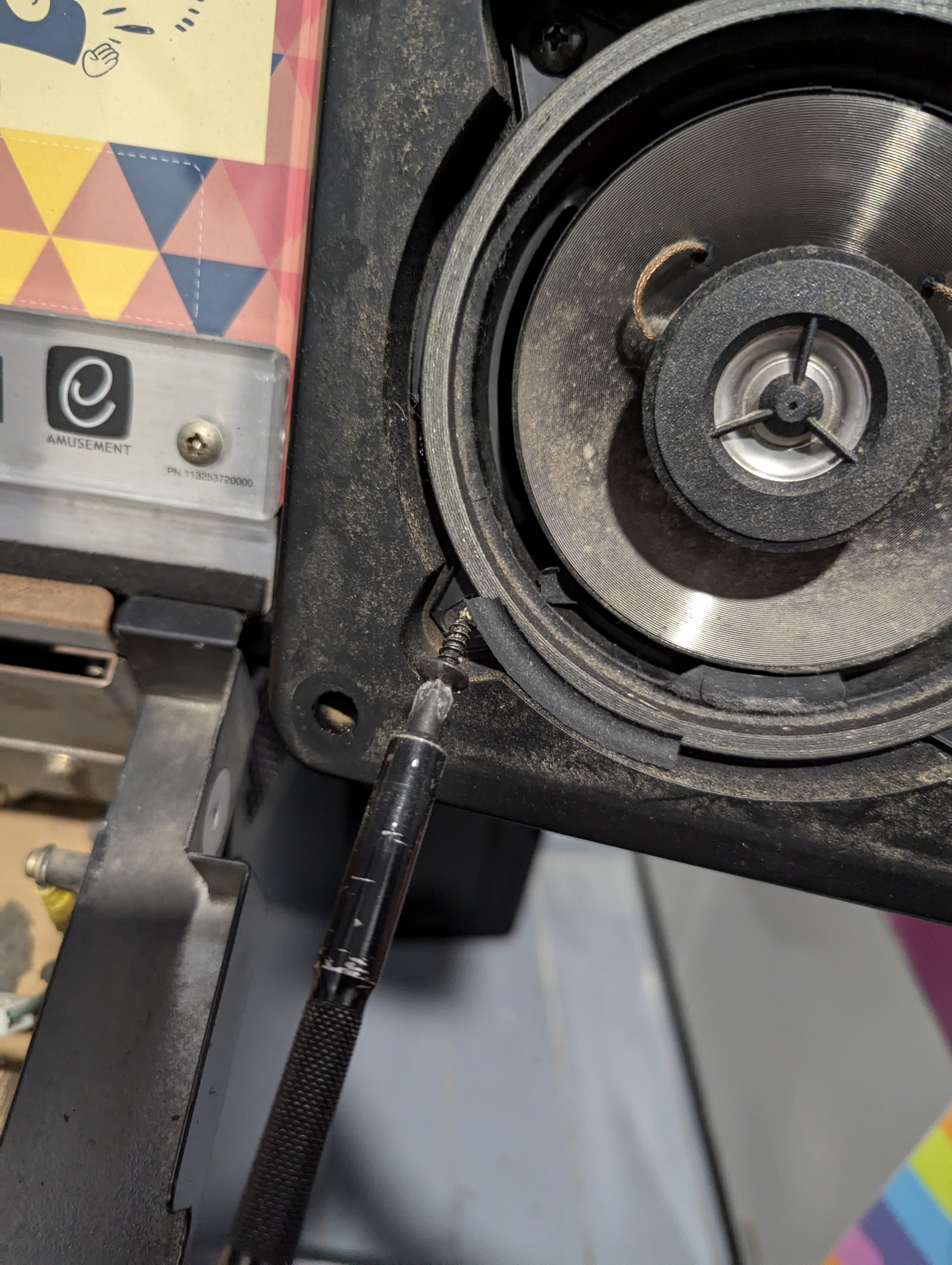 And you're done !The coaxial speakers in the top of the frame are 5" 1/4 (130mm). Any coaxial car speakers should fit in there as long as they use 4 mounting tabs.The subwoofer is 10" (250mm). If you're looking to replace it, the GRS 10SW-4 makes for a perfect replacement.
Who hurt you ?!Removing the speakers is rather easy, you will first need to remove the 4 screws from their coverBe careful not to drop the acrylic spacers that go at the back of the assemblyThen remove the 4 screws that hold the speaker in placeAnd you're done !The coaxial speakers in the top of the frame are 5" 1/4 (130mm). Any coaxial car speakers should fit in there as long as they use 4 mounting tabs.The subwoofer is 10" (250mm). If you're looking to replace it, the GRS 10SW-4 makes for a perfect replacement.